58MVP specifications
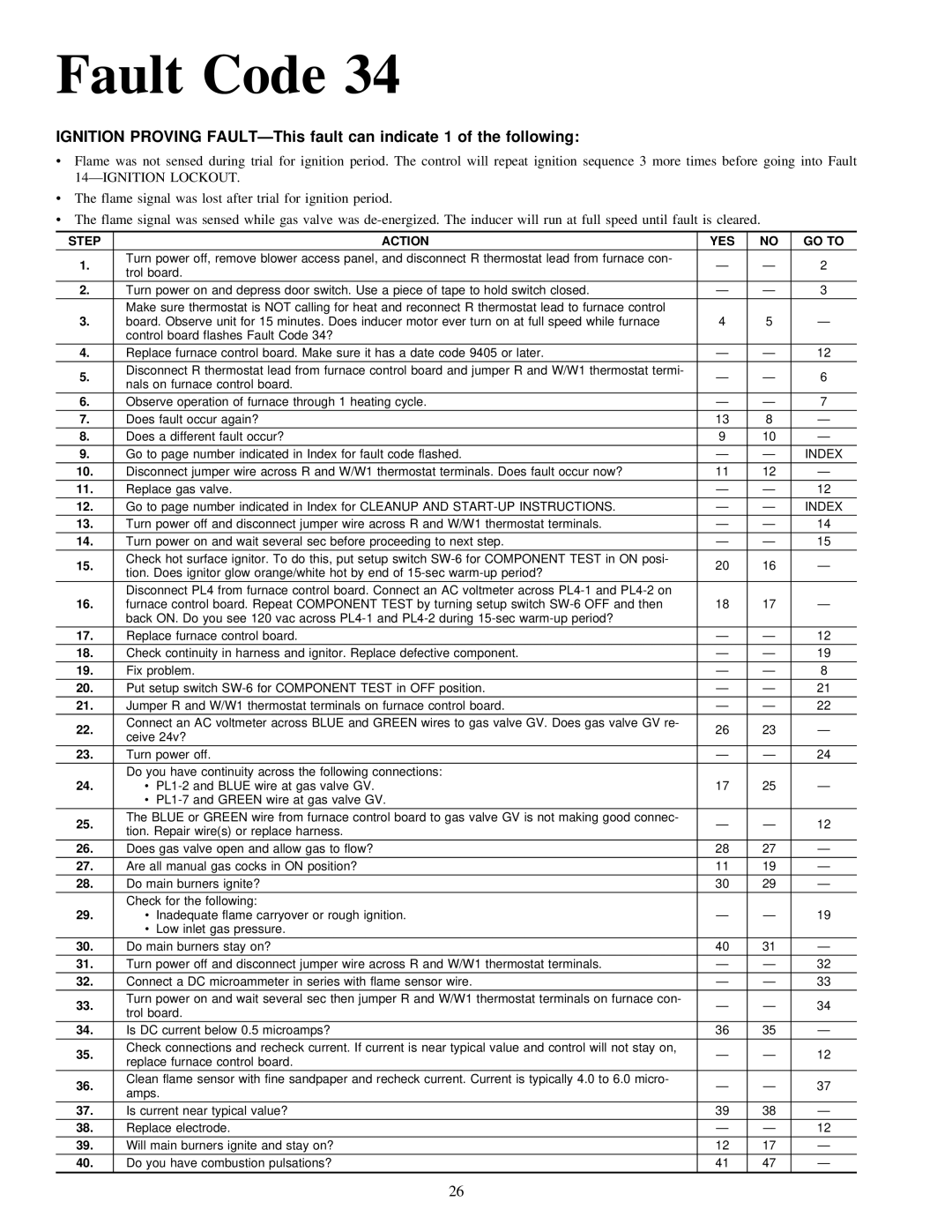
The Carrier 58MVP is a high-efficiency gas furnace designed for optimal performance and energy savings. This model represents Carrier's commitment to innovative engineering and advanced technology, making it a preferred choice for homeowners seeking reliable heating solutions.One of the standout features of the 58MVP is its impressive Annual Fuel Utilization Efficiency (AFUE) rating, which can reach up to 96 percent. This high AFUE rating indicates that the furnace uses less energy to produce heat, leading to lower utility bills and a reduced carbon footprint. The furnace is equipped with a two-stage gas valve that allows it to operate on a low setting during mild weather, providing increased efficiency and comfort.
The 58MVP also features Carrier's Infinity Control system, an advanced programmable thermostat that enables homeowners to customize their heating preferences. This system allows for precise temperature control and scheduling, ensuring that the home remains at a comfortable temperature while minimizing energy consumption.
In addition to its efficiency, the 58MVP is designed with noise reduction technology, including a quiet operating blower and insulated cabinet. This reduces operational sound, allowing for a more peaceful home environment. The model's multi-speed blower motor enhances comfort by providing consistent airflow and further optimizing efficiency.
Durability is a key characteristic of the Carrier 58MVP. It has a stainless-steel heat exchanger that promotes longevity and performance. The furnace is also equipped with a galvanized steel cabinet featuring a powder-coated finish, which protects against rust and corrosion.
The 58MVP is compatible with Carrier's advanced air purification systems, optimizing indoor air quality while heating. With features designed for efficiency, comfort, and durability, the Carrier 58MVP is an exceptional choice for homeowners looking to enhance their heating systems. The combination of advanced technologies, such as the two-stage operation and Infinity Control, positions this furnace as a leader in the market, meeting the needs of today's energy-conscious consumers. Ideal for both new constructions and retrofits, the Carrier 58MVP continues to set the standard for residential heating solutions.
