Carrier 58MVP instruction manual Fault Code, Step

Models: 58MVP

1 48
Download 48 pages 27.19 Kb
Page 29
Image 29

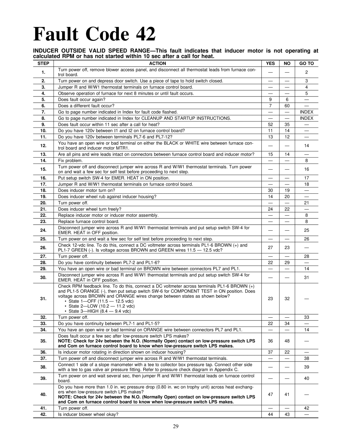
Fault Code 42

INDUCER OUTSIDE VALID SPEED RANGEÐThis fault indicates that inducer motor is not operating at calculated RPM or has not started within 10 sec after a call for heat.

STEP

ACTION

YES

NO

GO TO

1.

Turn power off, remove blower access panel, and disconnect all thermostat leads from furnace con-

Ð

Ð

2

trol board.


2.

Turn power on and depress door switch. Use a piece of tape to hold switch closed.

Ð

Ð

3

3.

Jumper R and W/W1 thermostat terminals on furnace control board.

Ð

Ð

4

4.

Observe operation of furnace for next 8 minutes or until fault occurs.

Ð

Ð

5

5.

Does fault occur again?

9

6

Ð

6.

Does a different fault occur?

7

60

Ð

7.

Go to page number indicated in Index for fault code flashed.

Ð

Ð

INDEX

8.

Go to page number indicated in Index for CLEANUP AND STARTUP INSTRUCTIONS.

Ð

Ð

INDEX

9.

Does fault occur within 11 sec after a call for heat?

52

35

Ð

10.

Do you have 120v between I1 and I2 on furnace control board?

11

14

Ð

11.

Do you have 120v between terminals PL7-6 and PL7-12?

13

12

Ð

12.

You have an open wire or bad terminal on either the BLACK or WHITE wire between furnace con-

Ð

Ð

14

trol board and inducer motor MTR1.


13.

Are all pins and wire leads intact on connectors between furnace control board and inducer motor?

15

14

Ð

14.

Fix problem.

Ð

Ð

8

15.

Turn power off and disconnect jumper wire across R and W/W1 thermostat terminals. Turn power

Ð

Ð

16

on and wait a few sec for self test before proceeding to next step.


16.

Put setup switch SW-4 for EMER. HEAT in ON position.

Ð

Ð

17

17.

Jumper R and W/W1 thermostat terminals on furnace control board.

Ð

Ð

18

18.

Does inducer motor turn on?

30

19

Ð

19.

Does inducer wheel rub against inducer housing?

14

20

Ð

20.

Turn power off.

Ð

Ð

21

21.

Does inducer wheel turn freely?

24

22

Ð

22.

Replace inducer motor or inducer motor assembly.

Ð

Ð

8

23.

Replace furnace control board.

Ð

Ð

8

24.

Disconnect jumper wire across R and W/W1 thermostat terminals and put setup switch SW-4 for

Ð

Ð

25

EMER. HEAT in OFF position.


25.

Turn power on and wait a few sec for self test before proceeding to next step.

Ð

Ð

26

26.

Check 12-vdc line. To do this, connect a DC voltmeter across terminals PL1-6 BROWN (+) and

27

23

Ð

PL1-7 GREEN (-). Is voltage across BROWN and GREEN wires 11.5 Ð 12.5 vdc?


27.

Turn power off.

Ð

Ð

28

28.

Do you have continuity between PL7-2 and PL1-6?

22

29

Ð

29.

You have an open wire or bad terminal on BROWN wire between connectors PL7 and PL1.

Ð

Ð

14


30.

Disconnect jumper wire across R and W/W1 thermostat terminals and put setup switch SW-4 for

Ð

Ð

31

EMER. HEAT in OFF position.


Check RPM feedback line. To do this, connect a DC voltmeter across terminals PL1-6 BROWN (+)


and PL1-5 ORANGE (-), then put setup switch SW-6 for COMPONENT TEST in ON position. Does


31.

voltage across BROWN and ORANGE wires change between states as shown below?

23

32

Ð

· State 1ÐOFF (11.5 Ð 12.5 vdc)


· State 2ÐLOW (10.2 Ð 11.2 vdc)


· State 3ÐHIGH (8.4 Ð 9.4 vdc)


32.

Turn power off.

Ð

Ð

33


33.

Do you have continuity between PL7-1 and PL1-5?

22

34

Ð


34.

You have an open wire or bad terminal on ORANGE wire between connectors PL7 and PL1.

Ð

Ð

14


Does fault occur a few sec after low-pressure switch LPS makes?


35.

NOTE: Check for 24v between the N.O. (Normally Open) contact on low-pressure switch LPS

36

48

Ð


and Com on furnace control board to know when low-pressure switch LPS makes.


36.

Is inducer motor rotating in direction shown on inducer housing?

37

22

Ð

37.

Turn power off and disconnect jumper wire across R and W/W1 thermostat terminals.

Ð

Ð

38

38.

Connect 1 side of a slope manometer with a tee to collector box pressure tap. Connect other side

Ð

Ð

39

with a tee to gas valve air pressure fitting. Refer to pressure check diagram in Appendix C.


39.

Turn power on and wait several sec, then jumper R and W/W1 thermostat leads on furnace control

Ð

Ð

40

board.


Do you have more than 1.0 in. wc pressure drop (0.80 in. wc on trophy unit) across heat exchang-


40.

ers when low-pressure switch LPS makes?

47

41

Ð

NOTE: Check for 24v between the N.O. (Normally Open) contact on low-pressure switch LPS


and Com on furnace control board to know when low-pressure switch LPS makes.


41.

Turn power off.

Ð

Ð

42

42.

Is inducer blower wheel okay?

44

43

Ð

29

Page 29
Image 29
Carrier 58MVP instruction manual Fault Code, Step