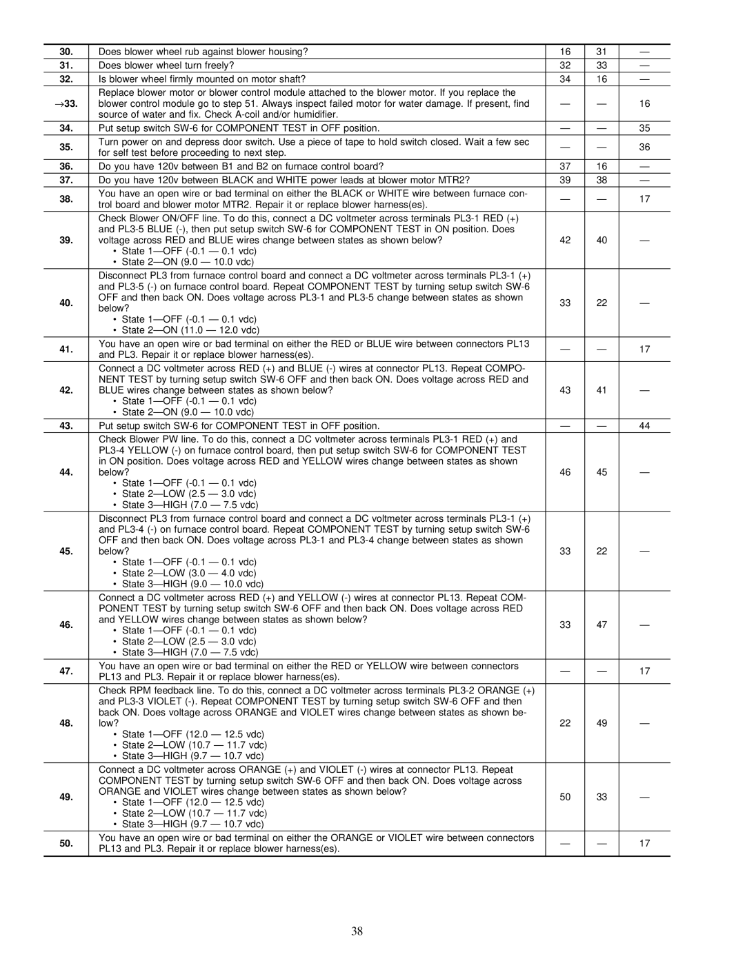
Carrier 58MVP instruction manual Does blower wheel rub against blower housing?

Models: 58MVP

1 48
Download 48 pages 27.19 Kb
Page 38
Image 38

30.

Does blower wheel rub against blower housing?

16

31

Ð

31.

Does blower wheel turn freely?

32

33

Ð

32.

Is blower wheel firmly mounted on motor shaft?

34

16

Ð

33.

Replace blower motor or blower control module attached to the blower motor. If you replace the


blower control module go to step 51. Always inspect failed motor for water damage. If present, find

Ð

Ð

16


source of water and fix. Check A-coil and/or humidifier.


34.

Put setup switch SW-6 for COMPONENT TEST in OFF position.

Ð

Ð

35

35.

Turn power on and depress door switch. Use a piece of tape to hold switch closed. Wait a few sec

Ð

Ð

36

for self test before proceeding to next step.


36.

Do you have 120v between B1 and B2 on furnace control board?

37

16

Ð

37.

Do you have 120v between BLACK and WHITE power leads at blower motor MTR2?

39

38

Ð

38.

You have an open wire or bad terminal on either the BLACK or WHITE wire between furnace con-

Ð

Ð

17

trol board and blower motor MTR2. Repair it or replace blower harness(es).


Check Blower ON/OFF line. To do this, connect a DC voltmeter across terminals PL3-1 RED (+)


39.

and PL3-5 BLUE (-), then put setup switch SW-6 for COMPONENT TEST in ON position. Does


voltage across RED and BLUE wires change between states as shown below?

42

40

Ð


·

State 1ÐOFF (-0.1 Ð 0.1 vdc)


·

State 2ÐON (9.0 Ð 10.0 vdc)


Disconnect PL3 from furnace control board and connect a DC voltmeter across terminals PL3-1 (+)


and PL3-5 (-) on furnace control board. Repeat COMPONENT TEST by turning setup switch SW-6


40.

OFF and then back ON. Does voltage across PL3-1 and PL3-5 change between states as shown

33

22

Ð

below?


·

State 1ÐOFF (-0.1 Ð 0.1 vdc)


·

State 2ÐON (11.0 Ð 12.0 vdc)


41.

You have an open wire or bad terminal on either the RED or BLUE wire between connectors PL13

Ð

Ð

17

and PL3. Repair it or replace blower harness(es).


Connect a DC voltmeter across RED (+) and BLUE (-) wires at connector PL13. Repeat COMPO-


42.

NENT TEST by turning setup switch SW-6 OFF and then back ON. Does voltage across RED and


BLUE wires change between states as shown below?

43

41

Ð


·

State 1ÐOFF (-0.1 Ð 0.1 vdc)


·

State 2ÐON (9.0 Ð 10.0 vdc)


43.

Put setup switch SW-6 for COMPONENT TEST in OFF position.

Ð

Ð

44


Check Blower PW line. To do this, connect a DC voltmeter across terminals PL3-1 RED (+) and


PL3-4 YELLOW (-) on furnace control board, then put setup switch SW-6 for COMPONENT TEST


44.

in ON position. Does voltage across RED and YELLOW wires change between states as shown


below?

46

45

Ð


·

State 1ÐOFF (-0.1 Ð 0.1 vdc)


·

State 2ÐLOW (2.5 Ð 3.0 vdc)


·

State 3ÐHIGH (7.0 Ð 7.5 vdc)


Disconnect PL3 from furnace control board and connect a DC voltmeter across terminals PL3-1 (+)


and PL3-4 (-) on furnace control board. Repeat COMPONENT TEST by turning setup switch SW-6


45.

OFF and then back ON. Does voltage across PL3-1 and PL3-4 change between states as shown


below?

33

22

Ð


·

State 1ÐOFF (-0.1 Ð 0.1 vdc)


·

State 2ÐLOW (3.0 Ð 4.0 vdc)


·

State 3ÐHIGH (9.0 Ð 10.0 vdc)


Connect a DC voltmeter across RED (+) and YELLOW (-) wires at connector PL13. Repeat COM-


PONENT TEST by turning setup switch SW-6 OFF and then back ON. Does voltage across RED


46.

and YELLOW wires change between states as shown below?

33

47

Ð

·

State 1ÐOFF (-0.1 Ð 0.1 vdc)


·

State 2ÐLOW (2.5 Ð 3.0 vdc)


·

State 3ÐHIGH (7.0 Ð 7.5 vdc)


47.

You have an open wire or bad terminal on either the RED or YELLOW wire between connectors

Ð

Ð

17

PL13 and PL3. Repair it or replace blower harness(es).


Check RPM feedback line. To do this, connect a DC voltmeter across terminals PL3-2 ORANGE (+)


and PL3-3 VIOLET (-). Repeat COMPONENT TEST by turning setup switch SW-6 OFF and then


48.

back ON. Does voltage across ORANGE and VIOLET wires change between states as shown be-


low?


22

49

Ð


·

State 1ÐOFF (12.0 Ð 12.5 vdc)


· State 2ÐLOW (10.7 Ð 11.7 vdc)


·

State 3ÐHIGH (9.7 Ð 10.7 vdc)


Connect a DC voltmeter across ORANGE (+) and VIOLET (-) wires at connector PL13. Repeat


COMPONENT TEST by turning setup switch SW-6 OFF and then back ON. Does voltage across


49.

ORANGE and VIOLET wires change between states as shown below?

50

33

Ð

·

State 1ÐOFF (12.0 Ð 12.5 vdc)


· State 2ÐLOW (10.7 Ð 11.7 vdc)


·

State 3ÐHIGH (9.7 Ð 10.7 vdc)


50.

You have an open wire or bad terminal on either the ORANGE or VIOLET wire between connectors

Ð

Ð

17

PL13 and PL3. Repair it or replace blower harness(es).


38

Page 38
Image 38
Carrier 58MVP instruction manual Does blower wheel rub against blower housing?