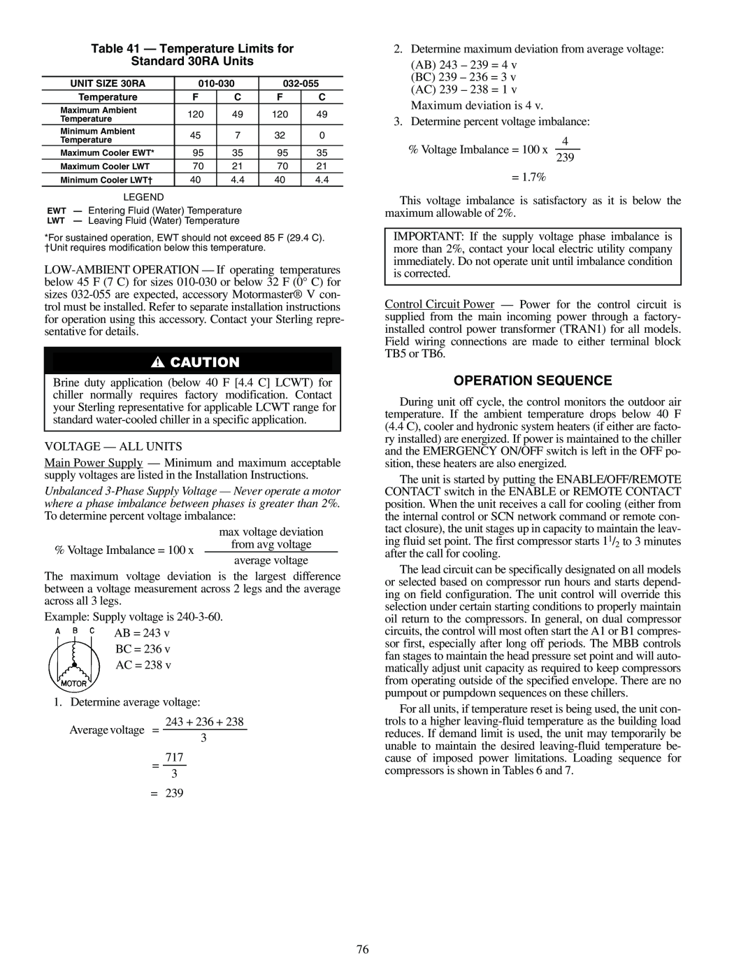
Table 41 — Temperature Limits for
Standard 30RA Units
UNIT SIZE 30RA | |||||
Temperature | F | C | F | C | |
Maximum Ambient | 120 | 49 | 120 | 49 | |
Temperature | |||||
|
|
|
| ||
Minimum Ambient | 45 | 7 | 32 | 0 | |
2.Determine maximum deviation from average voltage:
(AB) 243 – 239 = 4 v (BC) 239 – 236 = 3 v (AC) 239 – 238 = 1 v
Maximum deviation is 4 v.
3.Determine percent voltage imbalance:
Temperature |
|
|
|
|
Maximum Cooler EWT* | 95 | 35 | 95 | 35 |
% Voltage Imbalance = 100 x
4
Maximum Cooler LWT | 70 | 21 | 70 | 21 |
Minimum Cooler LWT† | 40 | 4.4 | 40 | 4.4 |
LEGEND
EWT — Entering Fluid (Water) Temperature
LWT — Leaving Fluid (Water) Temperature
*For sustained operation, EWT should not exceed 85 F (29.4 C).
†Unit requires modification below this temperature.
Brine duty application (below 40 F [4.4 C] LCWT) for chiller normally requires factory modification. Contact your Sterling representative for applicable LCWT range for standard
VOLTAGE — ALL UNITS
Main Power Supply — Minimum and maximum acceptable supply voltages are listed in the Installation Instructions.
Unbalanced
| max voltage deviation | |
% Voltage Imbalance = 100 x | from avg voltage | |
average voltage | ||
|
The maximum voltage deviation is the largest difference between a voltage measurement across 2 legs and the average across all 3 legs.
Example: Supply voltage is
BC = 236 v AC = 238 v
1. Determine average voltage:
243 + 236 + 238
Average voltage =
3
=7173
=239
239
= 1.7%
This voltage imbalance is satisfactory as it is below the maximum allowable of 2%.
IMPORTANT: If the supply voltage phase imbalance is more than 2%, contact your local electric utility company immediately. Do not operate unit until imbalance condition is corrected.
Control Circuit Power — Power for the control circuit is supplied from the main incoming power through a factory- installed control power transformer (TRAN1) for all models. Field wiring connections are made to either terminal block TB5 or TB6.
OPERATION SEQUENCE
During unit off cycle, the control monitors the outdoor air temperature. If the ambient temperature drops below 40 F (4.4 C), cooler and hydronic system heaters (if either are facto- ry installed) are energized. If power is maintained to the chiller and the EMERGENCY ON/OFF switch is left in the OFF po- sition, these heaters are also energized.
The unit is started by putting the ENABLE/OFF/REMOTE CONTACT switch in the ENABLE or REMOTE CONTACT position. When the unit receives a call for cooling (either from the internal control or SCN network command or remote con- tact closure), the unit stages up in capacity to maintain the leav- ing fluid set point. The first compressor starts 11/2 to 3 minutes after the call for cooling.
The lead circuit can be specifically designated on all models or selected based on compressor run hours and starts depend- ing on field configuration. The unit control will override this selection under certain starting conditions to properly maintain oil return to the compressors. In general, on dual compressor circuits, the control will most often start the A1 or B1 compres- sor first, especially after long off periods. The MBB controls fan stages to maintain the head pressure set point and will auto- matically adjust unit capacity as required to keep compressors from operating outside of the specified envelope. There are no pumpout or pumpdown sequences on these chillers.
For all units, if temperature reset is being used, the unit con- trols to a higher
76