OIL

RETURN LINE

CONNECTION

SERVICE

VALVES

CONDENSER

REFRIGERANT

COMPRESSOR

MOUNTING

WATER CONNECTIONS

INLET VALVE

SPRINGS

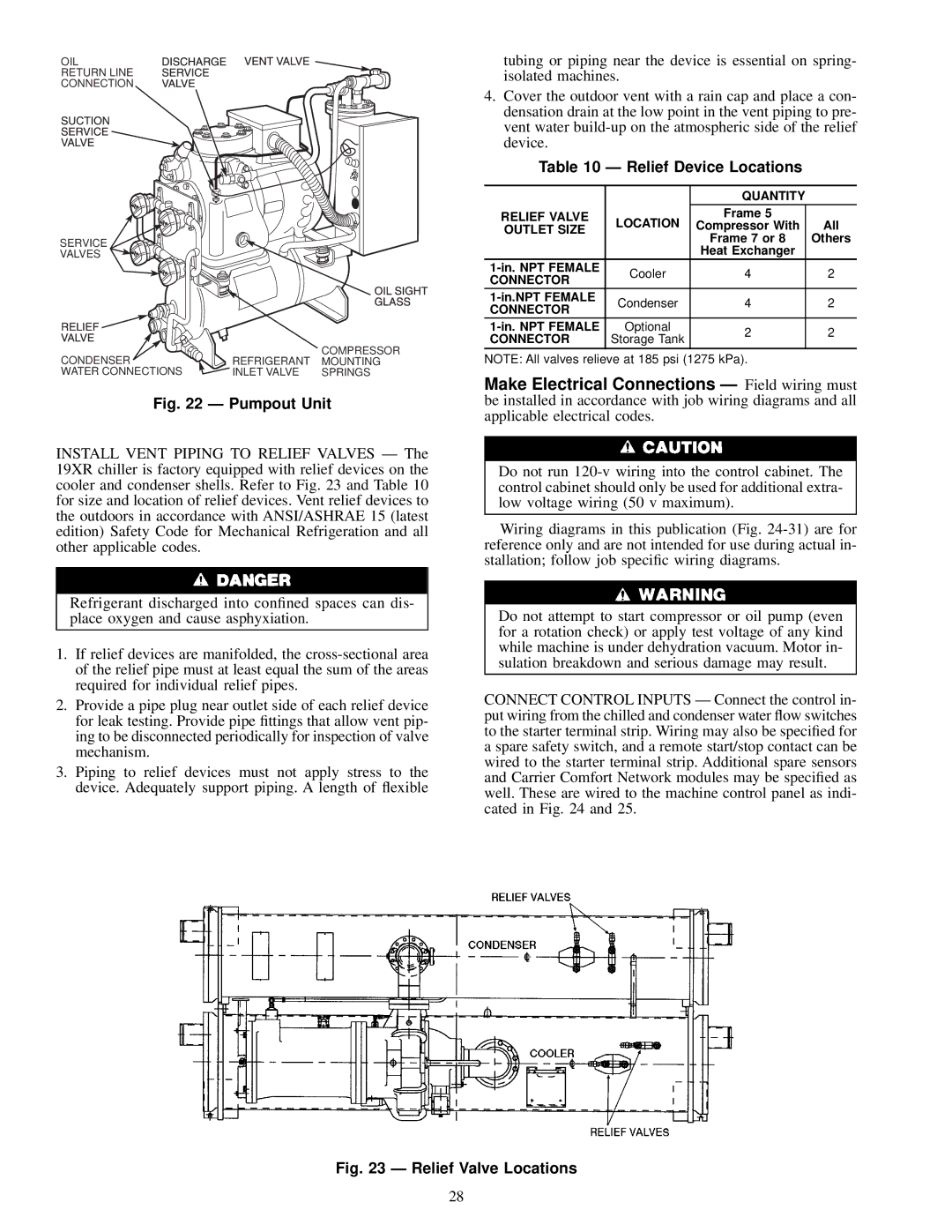
Fig. 22 Ð Pumpout Unit

INSTALL VENT PIPING TO RELIEF VALVES Ð The 19XR chiller is factory equipped with relief devices on the cooler and condenser shells. Refer to Fig. 23 and Table 10 for size and location of relief devices. Vent relief devices to the outdoors in accordance with ANSI/ASHRAE 15 (latest edition) Safety Code for Mechanical Refrigeration and all other applicable codes.

Refrigerant discharged into con®ned spaces can dis- place oxygen and cause asphyxiation.

1.If relief devices are manifolded, the cross-sectional area of the relief pipe must at least equal the sum of the areas required for individual relief pipes.

2.Provide a pipe plug near outlet side of each relief device for leak testing. Provide pipe ®ttings that allow vent pip- ing to be disconnected periodically for inspection of valve mechanism.

3.Piping to relief devices must not apply stress to the device. Adequately support piping. A length of ¯exible

tubing or piping near the device is essential on spring- isolated machines.

4.Cover the outdoor vent with a rain cap and place a con- densation drain at the low point in the vent piping to pre- vent water build-up on the atmospheric side of the relief device.

Table 10 Ð Relief Device Locations


QUANTITY


RELIEF VALVE

LOCATION

Frame 5


Compressor With

All

OUTLET SIZE


Frame 7 or 8

Others


Heat Exchanger


1-in. NPT FEMALE

Cooler

4

2

CONNECTOR


1-in.NPT FEMALE

Condenser

4

2

CONNECTOR


1-in. NPT FEMALE

Optional

2

2

CONNECTOR

Storage Tank


NOTE: All valves relieve at 185 psi (1275 kPa).

Make Electrical Connections Ð Field wiring must be installed in accordance with job wiring diagrams and all applicable electrical codes.

Do not run 120-v wiring into the control cabinet. The control cabinet should only be used for additional extra- low voltage wiring (50 v maximum).

Wiring diagrams in this publication (Fig. 24-31) are for reference only and are not intended for use during actual in- stallation; follow job speci®c wiring diagrams.

Do not attempt to start compressor or oil pump (even for a rotation check) or apply test voltage of any kind while machine is under dehydration vacuum. Motor in- sulation breakdown and serious damage may result.

CONNECT CONTROL INPUTS Ð Connect the control in- put wiring from the chilled and condenser water ¯ow switches to the starter terminal strip. Wiring may also be speci®ed for a spare safety switch, and a remote start/stop contact can be wired to the starter terminal strip. Additional spare sensors and Carrier Comfort Network modules may be speci®ed as well. These are wired to the machine control panel as indi- cated in Fig. 24 and 25.

Fig. 23 Ð Relief Valve Locations

28

Page 28
Image 28
Carrier 19XR installation instructions Relief Device Locations, Quantity Relief Valve, Outlet Size, Connector

19XR specifications

The Carrier 19XR and 19XRV chillers are sophisticated cooling solutions that represent the forefront of HVAC technology. Designed for large commercial and industrial applications, these chillers provide exceptional performance, energy efficiency, and reliability, making them ideal for a variety of environments ranging from hospitals to manufacturing facilities.

One of the most significant features of the Carrier 19XR and 19XRV chillers is their advanced scroll compressor technology. These units employ a tandem scroll design that enhances efficiency while minimizing operational noise. This makes them ideal for urban environments where noise restrictions may be in place. Moreover, the compressors are equipped with variable speed drive options in the 19XRV model, which allows for greater energy savings by adjusting cooling output based on real-time demand.

In addition to their advanced compressors, the 19XR and 19XRV units incorporate the Carrier GreenChoice refrigerant, which has a lower global warming potential compared to traditional refrigerants. This innovative choice not only meets regulatory requirements but also contributes to sustainability goals, making these chillers a responsible choice for environmentally conscious organizations.

The units are engineered with a robust heat exchanger design, which enhances heat transfer efficiency and overall system performance. This ensures optimal operation even in extreme conditions. They feature a microprocessor-based control system that allows for precise monitoring and control of the chiller’s performance, enabling operators to make real-time adjustments to maximize energy efficiency.

The Carrier 19XR and 19XRV chillers also prioritize serviceability. The design incorporates easy access to key components, simplifying maintenance procedures and reducing downtime. This focus on maintainability extends the lifespan of the equipment, leading to lower lifecycle costs.

In terms of connectivity, these chillers are equipped with advanced Building Management System (BMS) integration capabilities. This allows for seamless monitoring and control of the chillers using a centralized platform, facilitating energy management and operational optimization.

Overall, the Carrier 19XR and 19XRV chillers stand out in the market for their blend of cutting-edge technology, energy efficiency, and user-friendly features. They are engineered to meet the demanding needs of modern commercial and industrial applications, making them a preferred choice for facility managers seeking reliable cooling solutions.