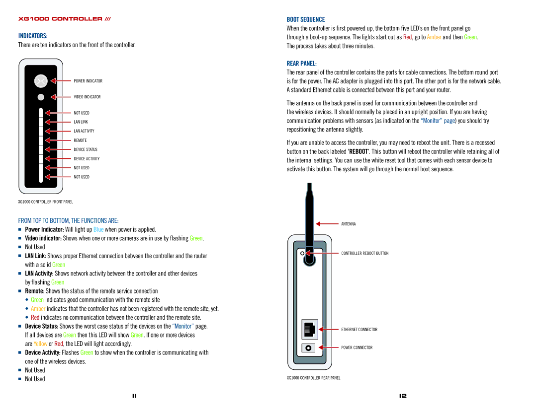
XG1000 specifications
The AT&T XG1000 is a cutting-edge device that has garnered significant attention for its robust performance and advanced features tailored for both residential and commercial users. This high-speed broadband gateway is designed to meet the increasing demands of modern-day connectivity, ensuring seamless internet access for multiple devices.One of the main features of the AT&T XG1000 is its support for fiber-optic technology, which allows for extraordinarily high data transfer speeds. With capabilities that can easily exceed 1 Gbps, the XG1000 is ideal for households and businesses that rely heavily on high-bandwidth applications such as video conferencing, online gaming, and 4K streaming. The device employs the latest advancements in fiber technology to provide stable and reliable internet connections, minimizing lag and buffering issues.
Equipped with advanced Wi-Fi 6 (802.11ax) technology, the XG1000 offers enhanced wireless performance. Wi-Fi 6 allows for improved capacity, speed, and efficiency, making it particularly effective in environments with multiple connected devices. Users can experience faster download and upload speeds, reduced latency, and better coverage, even in larger homes or offices.
The device also boasts a user-friendly interface that simplifies the setup process. Users can easily manage their network settings through a dedicated mobile app, which allows for features like parental controls, device prioritization, and guest network management. This level of control empowers users to customize their internet experience according to their individual needs.
In terms of security, the XG1000 incorporates advanced features such as built-in firewalls and encryption protocols, providing peace of mind for users concerned about online safety. Furthermore, it supports the latest security standards, ensuring that user data remains protected from potential threats.
The AT&T XG1000 is designed to be energy-efficient, aligning with modern environmental considerations. Its compact design allows for easy placement within various home or office settings without taking up excessive space.
Overall, the AT&T XG1000 stands out as a versatile and powerful internet gateway, equipped with the latest technologies to deliver fast, reliable, and secure internet access. Its blend of speed, efficiency, and user-friendly features makes it an excellent choice for anyone looking to enhance their connectivity experience, whether at home or in a business environment.

