Chapter 3
Operation
This chapter provides the following information for
•
•Operating procedures
Installation procedures given in Chapter 2 must be completed and checked before attempting to operate
3.1 Front Panel Indicators
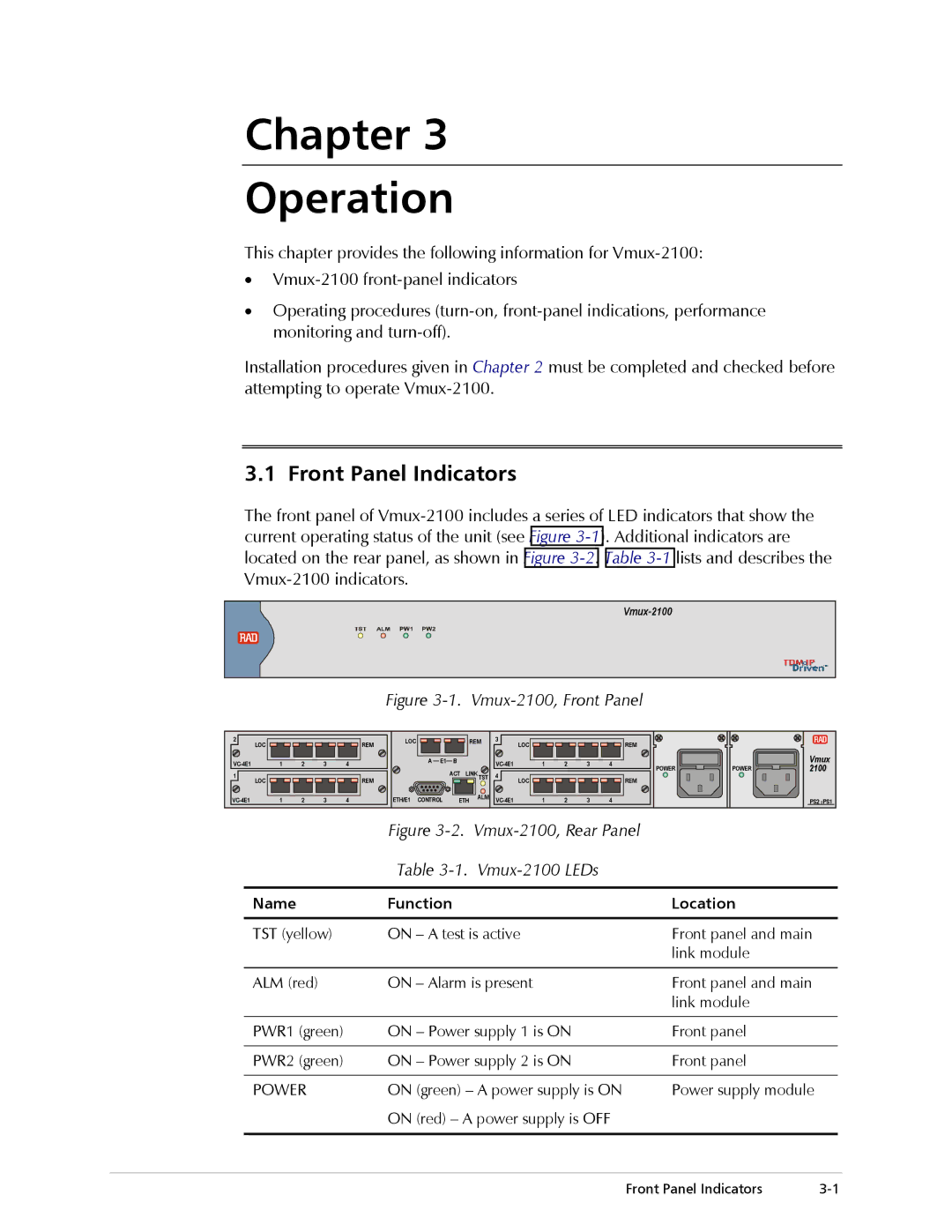
The front panel of
Figure 3-1. Vmux-2100, Front Panel
2 | LOC |
|
|
| REM | LOC |
|
|
| REM | 3 | LOC |
|
| REM |
|
|
|
|
|
|
|
|
|
|
|
|
|
|
|
|
|
| ||||
1 | 2 | 3 | 4 |
|
| A E1 | B |
|
| 1 | 2 | 3 | 4 |
|
| Vmux | ||
|
|
|
|
|
| POWER | POWER | 2100 | ||||||||||
1 |
|
|
|
|
|
|
| ACT | LINK TST | 4 |
|
|
|
| ||||
LOC |
|
|
| REM |
|
| LOC |
|
| REM |
|
|
| |||||
1 | 2 | 3 | 4 |
| ETH/E1 | CONTROL | ETH | ALM | 1 | 2 | 3 | 4 |
|
| PS2 PS1 | |||
|
|
|
| |||||||||||||||
|
|
|
|
|
| Figure |
|
|
|
| ||||||||
Table 3-1. Vmux-2100 LEDs
Name | Function | Location |
|
|
|
TST (yellow) | ON – A test is active | Front panel and main |
|
| link module |
|
|
|
ALM (red) | ON – Alarm is present | Front panel and main |
|
| link module |
|
|
|
PWR1 (green) | ON – Power supply 1 is ON | Front panel |
|
|
|
PWR2 (green) | ON – Power supply 2 is ON | Front panel |
|
|
|
POWER | ON (green) – A power supply is ON | Power supply module |
| ON (red) – A power supply is OFF |
|
|
|
|
Front Panel Indicators |