Appendix A
Interface Connector
Specifications
A.1 E1/T1 Ports
Balanced E1/T1 Interface Connector
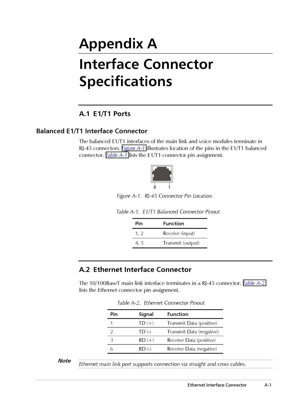
The balanced E1/T1 interfaces of the main link and voice modules terminate in
8 1
Figure A-1. RJ-45 Connector Pin Location
Table A-1. E1/T1 Balanced Connector Pinout
Pin | Function |
|
|
1, 2 | Receive (input) |
|
|
4, 5 | Transmit (output) |
|
|
A.2 Ethernet Interface Connector
The 10/100BaseT main link interface terminates in a
Table A-2. Ethernet Connector Pinout
Pin | Signal | Function |
|
|
|
1 | TD (+) | Transmit Data (positive) |
|
|
|
2 | TD | Transmit Data (negative) |
|
|
|
3 | RD (+) | Receive Data (positive) |
|
|
|
6 | RD | Receive Data (negative) |
|
|
|
Note | Ethernet main link port supports connection via straight and cross cables. |
|
Ethernet Interface Connector |