Chapter 5
Configuring Vmux-2100 for a Typical Application
This chapter gives detailed instructions for configuring
5.1 Application Requirements
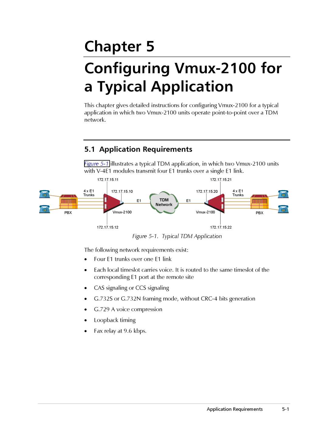
Figure 5-1 illustrates a typical TDM application, in which two Vmux-2100 units with V-4E1 modules transmit four E1 trunks over a single E1 link.
|
|
|
| 172.17.15.11 |
| 172.17.15.21 |
|
|
| |||||
|
|
| 4 x E1 | 172.17.15.10 |
| 172.17.15.20 |
|
| 4 x E1 | |||||
|
|
| Trunks |
|
|
|
| TDM |
|
|
| Trunks | ||
|
|
|
|
|
|
| E1 | E1 |
|
|
|
|
| |
|
|
|
|
|
|
|
| Network |
|
|
|
|
|
|
|
|
|
|
|
|
|
|
|
|
|
|
|
| |
|
| PBX |
|
|
|
|
|
| PBX | |||||
|
|
|
| 172.17.15.12 |
| 172.17.15.22 |
|
|
| |||||
Figure 5-1. Typical TDM Application
The following network requirements exist:
•Four E1 trunks over one E1 link
•Each local timeslot carries voice. It is routed to the same timeslot of the corresponding E1 port at the remote site
•CAS signaling or CCS signaling
•G.732S or G.732N framing mode, without
•G.729 A voice compression
•Loopback timing
•Fax relay at 9.6 kbps.
Application Requirements |