Appendix A Interface Connector Specifications | ||
|
|
|
|
|
|
|
|
|
A.3 CONTROL Connector
The control terminal interface terminates in a
Table A-3. CONTROL Connector Pinout
Pin | Function | Direction |
|
|
|
1 | Data Carrier Detect (DCD) | Out |
|
|
|
2 | Receive Data (RD) | In |
|
|
|
3 | Transmit Data (TD) | Out |
|
|
|
4 | Data Terminal Ready (DTR) | In |
|
|
|
5 | Ground (GND) | – |
|
|
|
6 | Data Set Ready (DSR) | Out |
|
|
|
7 | Request To Send (RTS) | In |
|
|
|
8 | Clear To Send (CTS) | Out |
|
|
|
9 | NC | – |
|
|
|
Note When connected and turned on, the terminal sets the DTR line ON (active) to gain
control over
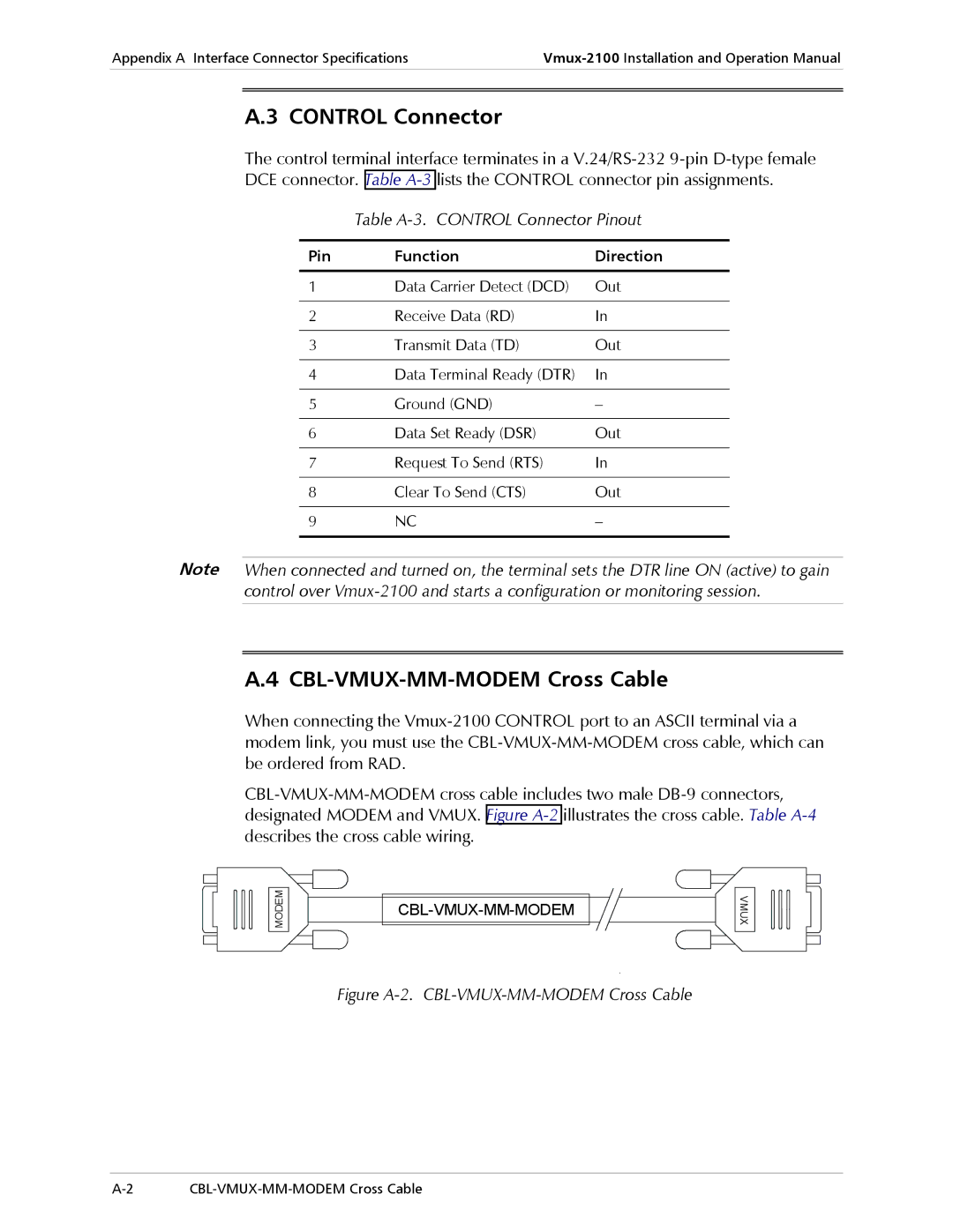
A.4 CBL-VMUX-MM-MODEM Cross Cable
When connecting the
MODEM
VMUX