Chapter 4 Management from a Terminal | |
|
|
Main Link 1 or Main Link 2
1.Connect > (Yes)
2.Frame > (G.732S)
3.Restoration Time> (CCITT)
4. Clock Source> (Lbt | (Local)) |
5.Interface Type> (Ltu)
6.Idle Code [0 - ff]... (ff)
@ - Db Update; # - Db Undo
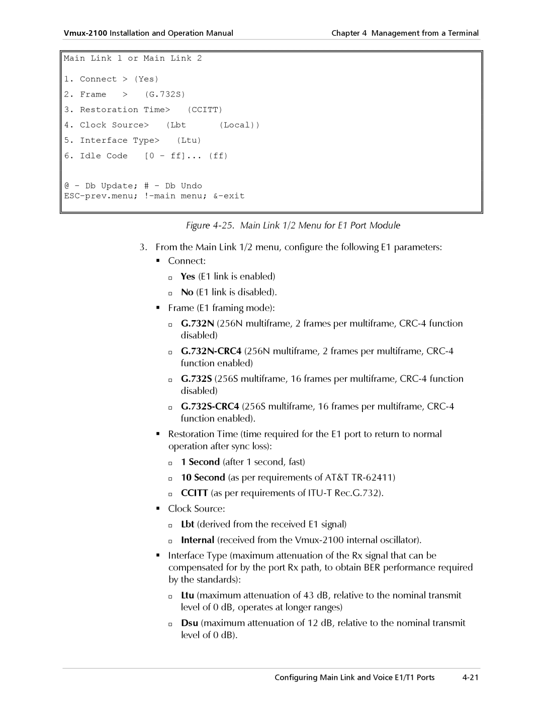
Figure 4-25. Main Link 1/2 Menu for E1 Port Module
3.From the Main Link 1/2 menu, configure the following E1 parameters: Connect:
Yes (E1 link is enabled) No (E1 link is disabled).
Frame (E1 framing mode):
G.732N (256N multiframe, 2 frames per multiframe,
G.732S (256S multiframe, 16 frames per multiframe,
Restoration Time (time required for the E1 port to return to normal operation after sync loss):
1 Second (after 1 second, fast)
10Second (as per requirements of AT&T
Clock Source:
Lbt (derived from the received E1 signal)
Internal (received from the
Interface Type (maximum attenuation of the Rx signal that can be compensated for by the port Rx path, to obtain BER performance required by the standards):
Ltu (maximum attenuation of 43 dB, relative to the nominal transmit level of 0 dB, operates at longer ranges)
Dsu (maximum attenuation of 12 dB, relative to the nominal transmit level of 0 dB).
Configuring Main Link and Voice E1/T1 Ports |
