|
|
|
|
| Configuring Channelized Data |
Configuring T1 and E1 Physical Ports |
|
| |||
Introduction |
|
|
|
| |
You have to configure the physical ports for the T1/E1 connections between the | |||||
| remote nodes and the PathBuilder S24x, 26x, and 27x switch. | ||||
| T1/E1 physical ports are configured as ports 49 and 50 on the PathBuilder S24x, 26x, | ||||
| and 27x switch. You can configure up to two T1 or E1 ports per node. | ||||
| There is an overall limitation of 30 Channelized Data ports for a T1 or E1 card | ||||
| installed in a node. The remaining ports can be used for voice traffic. | ||||
Configuration |
|
|
|
| |
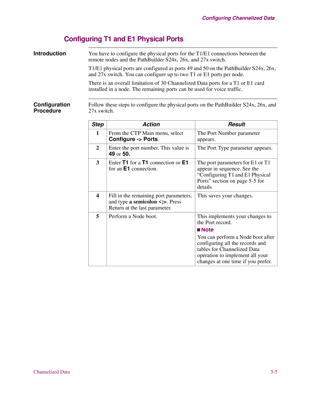
Follow these steps to configure the physical ports on the PathBuilder S24x, 26x, and | |||||
Procedure | 27x switch. |
|
| ||
|
|
|
|
|
|
| Step | Action |
|
| Result |
|
|
|
|
| |
| 1 | From the CTP Main menu, select |
| The Port Number parameter | |
|
| Configure |
| appears. | |
|
|
|
|
| |
| 2 | Enter the port number. This value is |
| The Port Type parameter appears. | |
|
| 49 or 50. |
|
|
|
|
|
|
|
| |
| 3 | Enter T1 for a T1 connection or E1 |
| The port parameters for E1 or T1 | |
|
| for an E1 connection. |
| appear in sequence. See the | |
|
|
|
| “Configuring T1 and E1 Physical | |
|
|
|
| Ports” section on page | |
|
|
|
| details. | |
|
|
|
|
| |
| 4 | Fill in the remaining port parameters, |
| This saves your changes. | |
|
| and type a semicolon <;>. Press |
|
|
|
|
| Return at the last parameter. |
|
|
|
|
|
|
|
| |
| 5 | Perform a Node boot. |
| This implements your changes to | |
|
|
|
| the Port record. | |
|
|
|
|
| Note |
|
|
|
|
| |
|
|
|
|
| |
|
|
|
| You can perform a Node boot after | |
|
|
|
| configuring all the records and | |
|
|
|
| tables for Channelized Data | |
|
|
|
| operation to implement all your | |
|
|
|
| changes at one time if you prefer. | |
|
|
|
|
|
|
Channelized Data |
