Configuring Channelized Data
Configuring Virtual Port Mapping Table
Introduction | A T1 or E1 digital port comprises multiple logical data channels. These channels, | |
| known as virtual ports, are not associated with any physical slot number and have no | |
| physical I/O of their own. |
|
Before You Begin |
| |
Obtain the timeslot assignments for all the remote nodes connecting to the | ||
| PathBuilder S24x, 26x, and 27x switch from your network services provider. You | |
| need this information to complete the virtual ports configuration. | |
Function |
| |
By configuring the Virtual Port Mapping Table, a timeslot channel on a specific T1 | ||
| or E1 line is mapped to a virtual port. Virtual ports are numbered from 100 to 254, | |
| whereas ports with actual physical connections are numbered from 1 to 54. | |
Configuration |
| |
The Virtual Port Mapping Table must be configured in conjunction with other | ||
Guidelines | records as follows. |
|
| • Configure the physical port record as either T1 or E1 and all virtual ports | |
| before you configure the Virtual Port Mapping Table. | |
| • Configure a Virtual Port Mapping Record to assign a timeslot number per | |
| T1/E1 channel for the application. | |
What You See |
| |
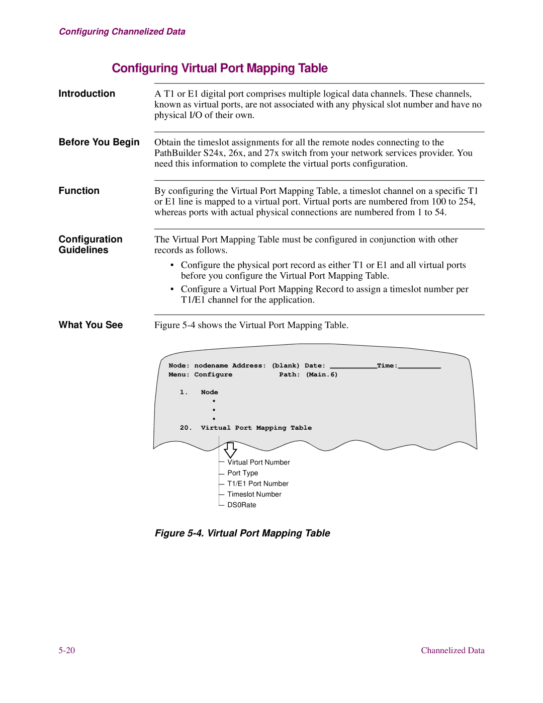
Figure | ||
| Node: nodename Address: (blank) Date: ___________Time:__________ | |
| Menu: Configure | Path: (Main.6) |
1. Node
•
•
•
20.Virtual Port Mapping Table
Virtual Port Number
Port Type
T1/E1 Port Number
Timeslot Number
DS0Rate
Figure 5-4. Virtual Port Mapping Table
Channelized Data |
