3Com Corporation
Restricted Rights Legend
Restricted Rights Notification for U.S. Government Users
Proprietary Material
Page
Contents
Appendix A. Cables
Introduction
Overview
Audience
Manual
Trademarks
About This Manual
Switch?
What is
PathBuilder S24x
26x,
Application
Meshed Cluster
Support
Performance
Applications
Branch Nodes
Concentrator
Regional
Regional Concentrator Example
PathBuilder S24x, 26x, and 27x Switch Cluster Example
Description
Features and Protocols
Hardware Components
PathBuilder S24x, 26x, and 27x Switch Hardware Configuration
Components
Hardware
Component Description
DSPM/SM
Ethernet Port 4 Limitations
Enclosure
Parts
Motherboard
Motherboard
Ports
Flash Simm
Slot Number Port Number Associated Card
Port Numbers
Serial/Network
Port Number Use
Used
DIMs without a Cable Adapter DIMs with a Cable Adapter
Back Panel Components
Back Panel
Function
TI Dual Port Digital PBX Interface Card
Cable Description Function
LED Status
Indicators
Color LED is Indicating
E1 Dual Port Digital PBX Interface Card
Settings
DIP Switch
PBX Interface Card Illustration
Location
Sysfail
RUN
Step Action
DSPM/SM Card
13. DSPM/SM Card
14. Cabling T1/E1 Card to DSPM/SM Cards
Dspm Card with Analog E&M Interface
15. DSPM/E&M Card
LEDs
Default Jumper
Setting Jumpers for Dspm Card with Analog E&M Interface
Settings
Jumper Wire/600 Wire/UK Number Complex
16. UK Complex Impedance
Germany
18. Jumper Locations for Dspm E&M Card
Dspm Card with FXS Analog Interface
20. Dspm Card with Analog FXS Interface
For Australian
Jumper Locations
Users
Dspm Host Card with FXO Analog Interface
21. DSPM/HC Card with Analog FXO Daughtercard
Card Illustration
Hardware Components
48V Ringer/Power Supply Card and Enclosure
22. Standard -48V RInger/Power Supply Card and Enclosure
23. Enhanced -48V RInger/Power Supply Card and Enclosure
24 BaseT Transceiver
10BaseT Transceiver
Canadian DOC
Radio Frequency Interference Regulations
General
Telecommunications Regulations
Mise en Garde
FCC and Telephone Company Procedures and Requirements
FCC Information
Concerning
Regulations
Electromagnetic
Radiation
FCC Information
Preparation and Unpacking
Operating
Selecting an
Environment
Mise en Garde
Checking
Unpacking
PathBuilder S24x, 26x, and 27x Switch Rackmount Kit
Considerations
Placement
PathBuilder S24x, 26x, and 27x Switch Rackmount Kit
Step Action Description
Step Action Description
Pedestal Base
Removing
Steps for
Rackmount Assembly
Installing the PathBuilder S24x, 26x, and 27x Switch
Installation
PathBuilder S24x, 26x, and 27x Switch Hardware
Avertissement
Switches 1
Setting DIP Switches
Switch Settings for Motherboard Switches 1
Set Switch For
DSU DIM Installation
Installing the DSU DIM
Step Action Result/Description
Switch Settings
Procedure
Configuration
INT
EXT
Input Signals
DSU Input and Output Signaling
Output Signals
Signal Description
CLK
IDL
Loopback Options
Troubleshooting
Troubleshooting DSU Installation
If Problems Arise
DIM
Example
Installing DIMs
Mise en Garde
Installing SIMMs
Installing SIMMs
Installing an I/O
Installing I/O Cards
BRI
Installation
Installing a T1 or E1 Dual Port Digital PBX Interface Card
Place the interface card on an antistatic mat
Installing the T1/CSU Daughter Card
Follow these steps to install the T1/CSU Daughter card
Installing T1/CSU Daughter Cards
LAN
Cabling the PathBuilder S24x, 26x, and 27x Switch
Transceiver
Installing the Transceiver
Power Up
Power-Up Diagnostics/Verification
Sequence
Function Description
Command
Default Node
Setting Node to
Default
Installing Software Options
Full Mesh Cluster Cabling
Configuring
Usage
Cables
Mesh Diagram
Maintenance
Maintenance
Cover
Removing/Replacing Top Cover
Removing the Top Cover
Panel Cover
Removing/Replacing Front Panel Cover
Removing the Front Panel Cover
Supply
Removing/Replacing Power Supply
Removing the Power Supply
Expansion Card
Removing an
Removing the Support Bar
Removing an Expansion Card
Replacing PathBuilder S24x, 26x, and 27x Switch Motherboard
Removing the Motherboard
Install
Battery
Removing/Replacing the Lithium Battery
Replacing
Removing the Lithium Battery
Removing/Replacing the Lithium Battery
Alarms
What Is It?
Statistics
Software
Overview
Application Example
Configure this Record/Table To do this
Configuring Channelized Data
Configuring Channelized Data
Configure Ports
Configuring T1 and E1 Physical Ports
Step Action Result
49 or
Port Record
Menu Configure Path Main.6 Node Port
Parameters Port Number
Guidelines
Port Type
Line Framing Type
INT, REC
Transmit Clock
Line Build Out
Facility Data Link
Threshold Value-LCV
Threshold Value LES
Threshold Value-PCV
Threshold Value-CSS
Threshold Value-BES
Threshold Value-ES
Threshold Value Sefs
Threshold Value-SES
Threshold Value UAS
Parameters Port Type
E1 Port Record
Line Coding
Line Impedance
Threshold Value-CSS
Threshold Value-SES
Threshold Value UAS
How to
Booting Virtual
Enabling/ Disabling
Virtual Ports
Port Configuration for Channelized Data Option
What You See
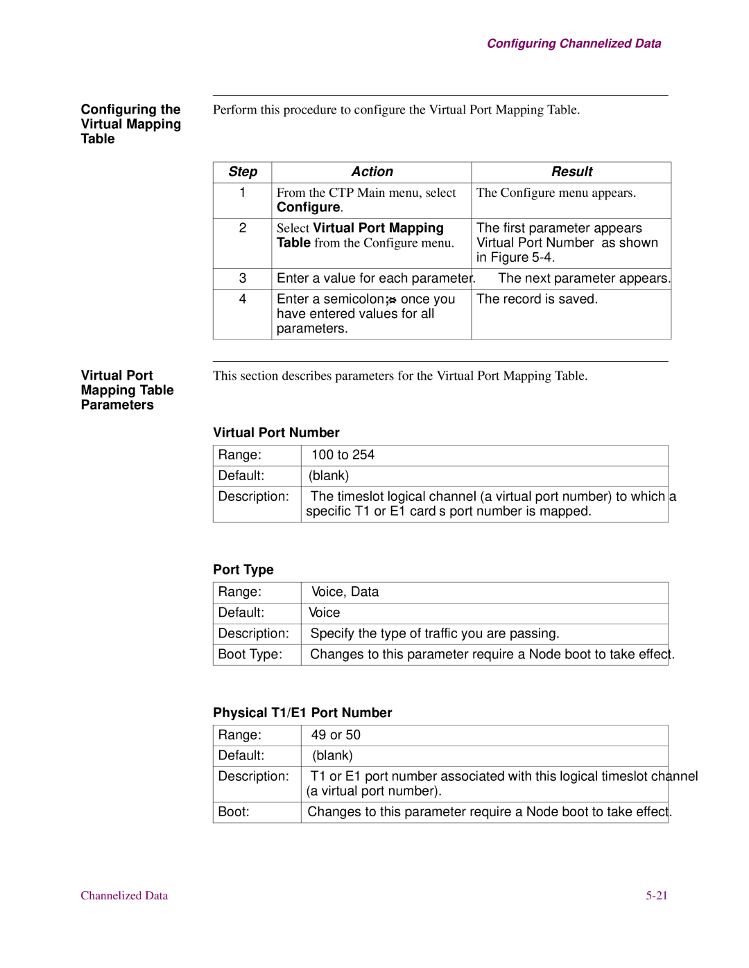
Configuring Virtual Port Mapping Table
Virtual Mapping
Configure Select Virtual Port Mapping
Virtual Port
Mapping Table Parameters Virtual Port Number
DS0 Rate
Time Slots
Function/Signal Pin
EIA 232-D Signals Motherboard and SDB
Function/Signal Name
Pin
35/V.36 Motherboard
Position Signal Name
Function Pin
External Transmit Clock B Clock a Test Mode
Function/Signal
35/V.36 SDB
Receive Receive Clock Clock B Data Data Terminal Ready
Position Signal
V11 Signals Motherboard
V11 Signals SDB
Pin Signal
Additional Information Ethernet RJ-45S Connector Signals
Ethernet Cable Pinouts
+12V
Ethernet Cable Pinouts
AC Input
Power Output
DC Input
PathBuilder S24x, 26x, and 27x Switch Specifications
Numeric Status Service Description/Comments Display
Error Codes
Numeric Status Service Description/Comments
Technical Support
3ComFacts Automated Fax Service
Access by Analog Modem
Access by Digital Modem
Country Data Rate Telephone Number
3Com
Support from
Country Telephone Number
Country Telephone Number Fax Number
Numerics
Index
CTP
FCC
DSU
Index-3
URL D-1
Simm
Disabling Warm Restart World Wide Web WWW D-1
Index-6