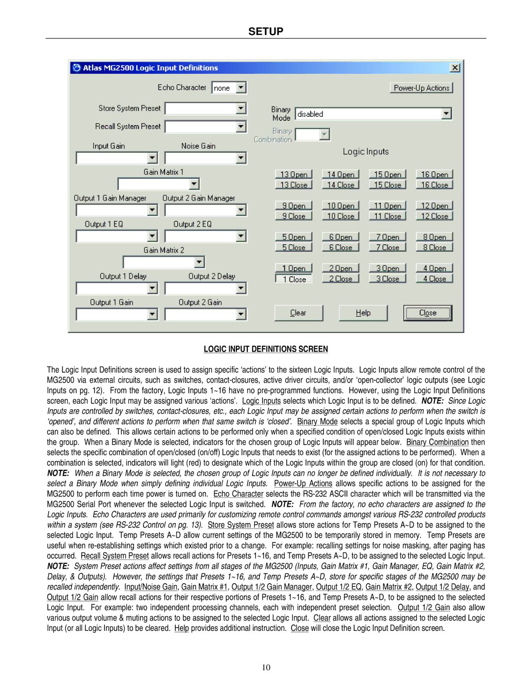
MG2500 specifications
The Atlas Sound MG2500 is a robust and versatile professional audio mixer designed to meet the demands of various applications, including live sound, broadcasting, and recording environments. This mixer stands out for its exceptional build quality, intuitive layout, and advanced features, making it a favorite among audio professionals.One of the main features of the MG2500 is its configuration, which typically includes 16 channels, allowing for extensive input options. Each channel is equipped with high-quality preamps that ensure clean and clear signal transfer. The mixer offers both XLR and quarter-inch inputs, accommodating a variety of microphones and instruments. Additionally, the MG2500 provides phantom power, enabling the use of condenser microphones that require an external power source.
The MG2500 incorporates a 3-band equalization on each channel, consisting of low, mid, and high-frequency controls. This feature allows users to enhance or reduce specific frequency ranges, tailoring the sound to fit the environment and accommodating various audio sources. The inclusion of multiple auxiliary sends enables stage monitoring and effects processing, enhancing flexibility in live settings.
One of the standout technologies in the MG2500 is its onboard digital effects processor. This feature offers a wide range of customizable effects, such as reverb and echo, which can be applied to any channel, enriching the overall sound experience. The user-friendly interface makes accessing these effects straightforward, allowing for quick adjustments during performances.
The mixer also caters to modern audio needs with USB connectivity, facilitating easy integration into digital audio workstations (DAWs). This function makes recording and playback seamless, appealing to both live sound engineers and studio producers. Furthermore, the MG2500 is designed to withstand the rigors of live performances, featuring a durable chassis that ensures longevity and reliability under demanding conditions.
In terms of output options, the MG2500 includes multiple main and monitor outputs, allowing for flexible routing and connection to various sound systems. Additionally, the built-in audio limiter helps prevent signal clipping, ensuring clear and undistorted sound at high volume levels.
With its powerful features and robust construction, the Atlas Sound MG2500 is an excellent choice for professionals seeking a reliable and flexible audio mixer capable of delivering superior sound quality across various applications.

