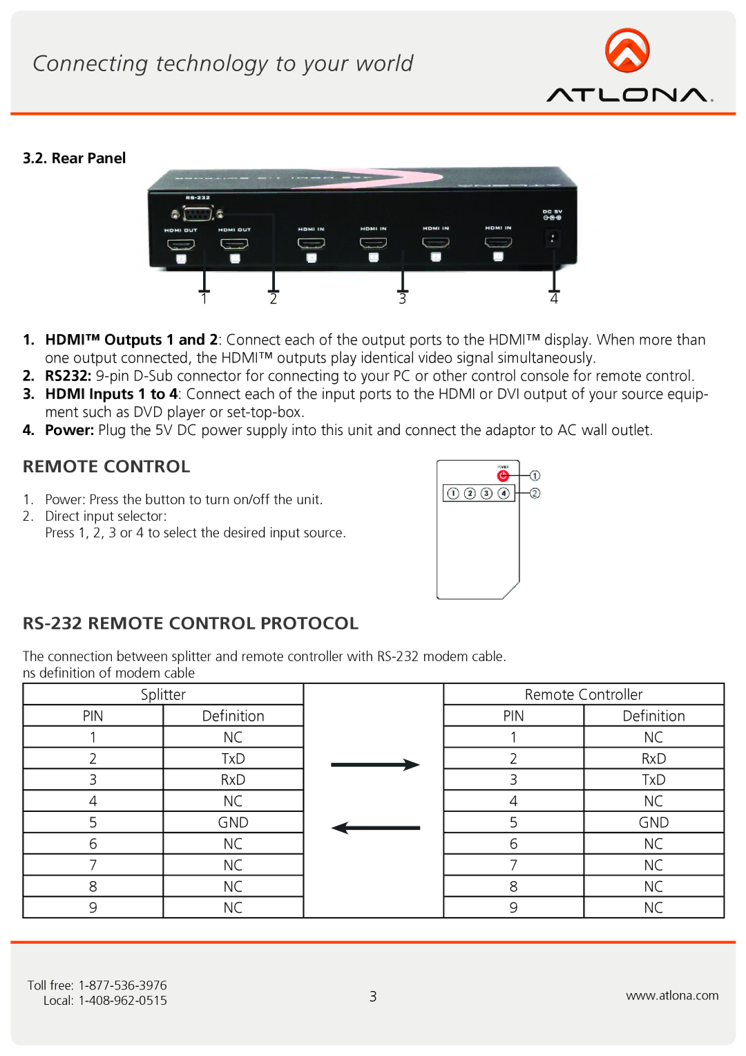
3.2. Rear Panel
1 | 2 | 3 | 4 |
1.HDMI™ Outputs 1 and 2: Connect each of the output ports to the HDMI™ display. When more than one output connected, the HDMI™ outputs play identical video signal simultaneously.
2.RS232:
3.HDMI Inputs 1 to 4: Connect each of the input ports to the HDMI or DVI output of your source equip- ment such as DVD player or
4.Power: Plug the 5V DC power supply into this unit and connect the adaptor to AC wall outlet.
REMOTE CONTROL
1.Power: Press the button to turn on/off the unit.
2.Direct input selector:
Press 1, 2, 3 or 4 to select the desired input source.
RS-232 REMOTE CONTROL PROTOCOL
The connection between splitter and remote controller with
| Splitter | |
PIN |
| Definition |
1 |
| NC |
2 |
| TxD |
3 |
| RxD |
4 |
| NC |
5 |
| GND |
6 |
| NC |
7 |
| NC |
8 |
| NC |
9 |
| NC |
|
|
|
| Remote Controller | |
PIN |
| Definition |
1 |
| NC |
2 |
| RxD |
3 |
| TxD |
4 |
| NC |
5 |
| GND |
6 |
| NC |
7 |
| NC |
8 |
| NC |
9 |
| NC |
|
|
|
Toll free: | 3 | www.atlona.com |
Local: |
