Hardware Description
2.5.2 | Solder straps | Solder straps allow to modify the board configuration for specific usage such as | |||
|
|
| T89C51CC02 compatibility. |
| |
Table |
|
|
| ||
Reference | PCB Name |
| Comments (guidelines) | Default | |
|
|
|
|
|
|
SP1 |
| CC02 & C5115 |
| For T89C51CC02 usage, allows to redirect the ISP signal to P1.0, for | Open |
| mode |
| hardware conditions. | ||
|
|
|
| ||
|
|
|
|
|
|
SP2 |
| X2_44 |
| Connect PLCC44 Xtal2 to XTAL2 of the generic extension board (optionnal) | Open |
|
|
|
|
|
|
SP3 |
| X2_52 |
| Connect PLCC52 Xtal2 to XTAL2 of the generic extension board (optionnal) | Open |
|
|
|
|
|
|
Figure
| “Open” |
|
| “Close” | ||||||
|
|
|
|
|
|
|
|
| ||
|
|
|
|
|
|
|
|
|
|
|
Solder Pad | Solder gout |
|
| |||||||
|
|
|
| |||||||
| ||||||||||
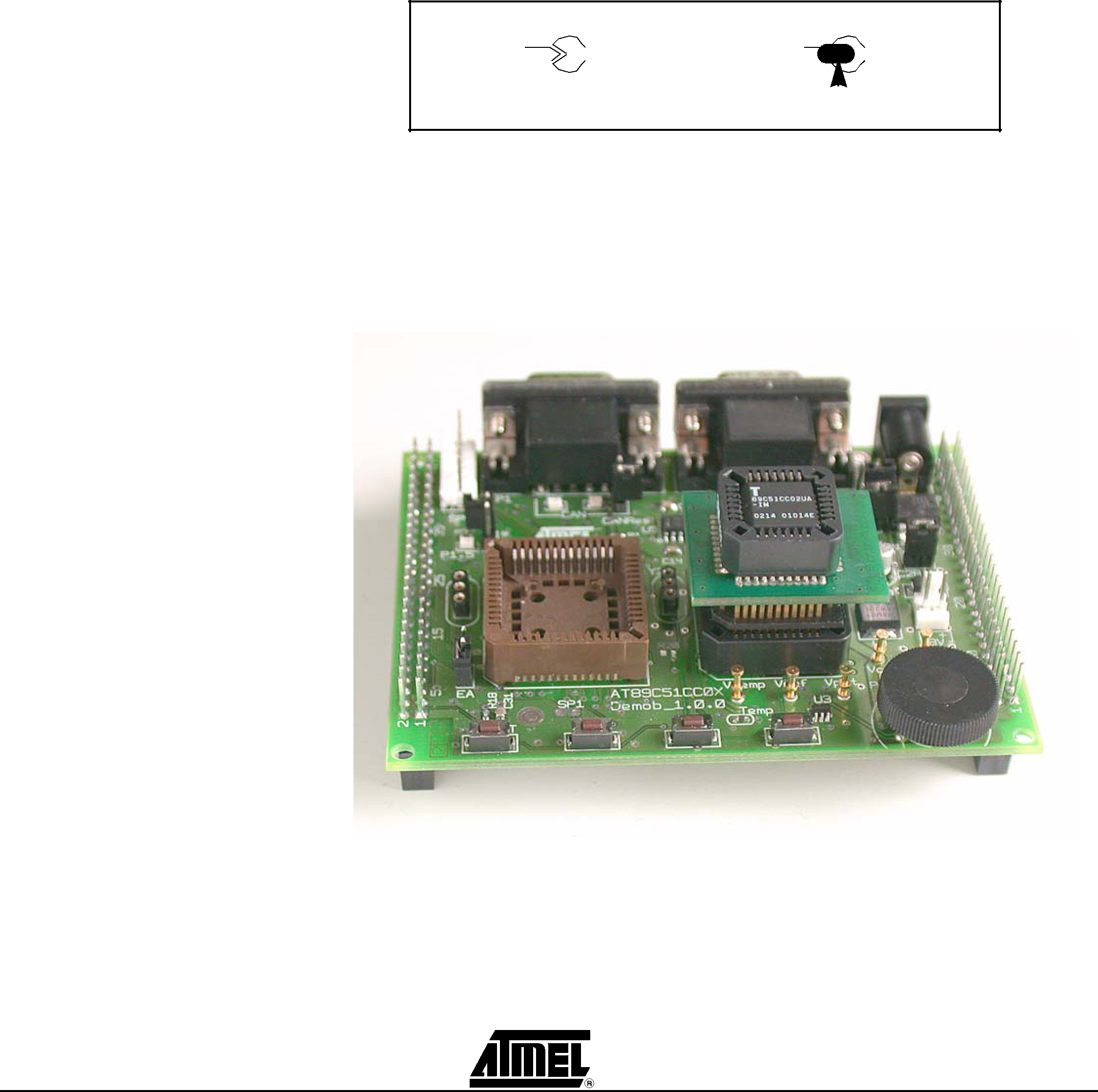
2.5.2.1T89C51CC02/T89C5115When using T89C51CC02 or T89C5115 products with the
| Support (SP1) | ¨PLCC adapter for T89C51CC02 user guide: CANADAPT28), the SP1 solder pad |
| should be closed to ensure correct hardware conditions setting on P1.0 port. |
| SP1 solder pad connects ISP push button to P1.0 microcontroller port and the |
| CANADAPT28 adapter should be inseted in U2 (PLCC44) socket. |
| Figure |