To set up cabling and termination:
1Determine whether your ATTO Express PCI adapter is a single channel or dual channel model. One external connector indicates a single channel host adapter; two external connectors indicate a dual channel host adapter.
2Determine if SCSI devices will be installed internally or externally.
Total bus cable length, varies by host adapter and type of attached devices. Refer to Exhibit
If you combine Wide
Wide devices first (closest to the connector).
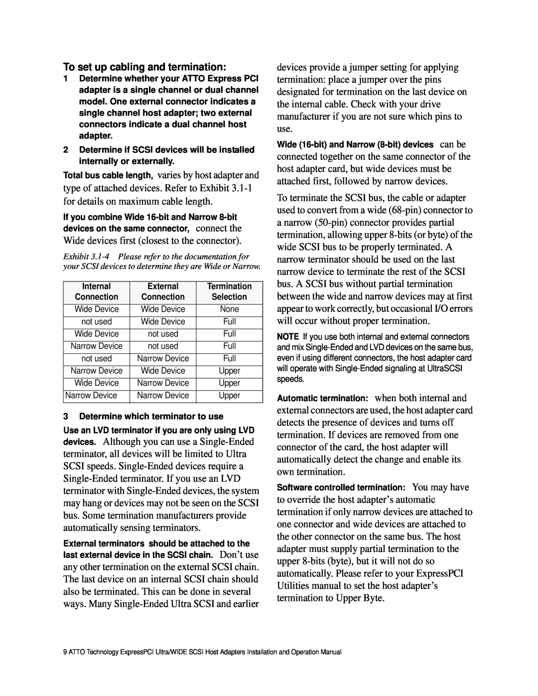
Exhibit
Internal | External | Termination |
Connection | Connection | Selection |
Wide Device | Wide Device | None |
|
|
|
not used | Wide Device | Full |
|
|
|
Wide Device | not used | Full |
|
|
|
Narrow Device | not used | Full |
|
|
|
not used | Narrow Device | Full |
|
|
|
Narrow Device | Wide Device | Upper |
|
|
|
Wide Device | Narrow Device | Upper |
|
|
|
Narrow Device | Narrow Device | Upper |
|
|
|
3 Determine which terminator to use
Use an LVD terminator if you are only using LVD
devices. Although you can use a
External terminators should be attached to the
Don’t use any other termination on the external SCSI chain. The last device on an internal SCSI chain should also be terminated. This can be done in several ways. Many
devices provide a jumper setting for applying termination: place a jumper over the pins designated for termination on the last device on the internal cable. Check with your drive manufacturer if you are not sure which pins to use.
Wide
connected together on the same connector of the host adapter card, but wide devices must be attached first, followed by narrow devices.
To terminate the SCSI bus, the cable or adapter used to convert from a wide
NOTE If you use both internal and external connectors and mix
when both internal and
external connectors are used, the host adapter card detects the presence of devices and turns off termination. If devices are removed from one connector of the card, the host adapter will automatically detect the change and enable its own termination.
Software controlled termination: You may have
to override the host adapter’s automatic termination if only narrow devices are attached to one connector and wide devices are attached to the other connector on the same bus. The host adapter must supply partial termination to the upper
9 ATTO Technology ExpressPCI Ultra/WIDE SCSI Host Adapters Installation and Operation Manual