¨
3
Heavy Duty Bilge Pump
4030, 4060, 4031, 4061 Installation Instructions
Attwood marine hardware, navigational lighting, bilge pumps, and other marine accessories are specified more than any other brand by AmericaÕs
SAVE THESE INSTRUCTIONS
Form Number 69317 Rev. D | 03/10 |
FEATURES
Attwood Heavy Duty Bilge Pumps are the newest development in high output pumps. All models have a removable housing for simple installation and easy cleaning. They connect to
or 4202.
AUTOMATIC OPERATION
All boats over 20' (6.1 m) in length which have sleeping accommodations (excluding
MANUAL OPERATION
For manual operation of your bilge pump system, disregard the references to Automatic Float Switch installation and operation.
Check the chart below to select the proper pump, fuse size, and
Pump |
|
|
|
|
|
Part | Pump |
| Amp | Outlet Hose | |
Number | Model | Volts | Fuse | Inside Dia. | Connector |
|
|
|
|
|
|
4030, 4031 | HD1700 | 12VDC | 10 | 3874 | |
4060, 4061 | HD2000 | 12VDC | 12 |
| 3874 |
Recommendations are based on amount of gallons exhausted per hour (GPH). GPH measurements are typical of production pumps tested using
The chart below shows gallons and liters per hour ratings for 0' head and 3' (91.4 cm) head. GPH/LPH may also vary depending on power source, hose type, and other variables.
| ABYC Specifications |
| ISO Specifications |
| ||
| 13.6 volts DC |
| 12.0 volts DC |
| ||
| (GPH=Gallons Per Hour) | (LPH=Liters Per Hour) |
| |||
|
| GPH | LPH | GPH | LPH |
|
Part |
| Open | Open | 3' | 3' | Amp |
No. | Model | Flow | Flow | Head | Head | Draw |
|
|
|
|
|
|
|
4030, 4031 | HD1700 | 1,700 | 6,450 | 1,300 | 4,920 | 6.0 |
4060, 4061 | HD2000 | 2,000 | 7,600 | 1,550 | 5,867 | 8.0 |
The pumps can run dry for limited periods of time; however, doing so could cause pump failure.
WARNING:
To prevent personal injury, always disconnect the power source when installing or servicing any electrical product. Remove vessel from water when using any 110/120 or 220 Volt AC power tools.
DO NOT use pump to remove gasoline, oil or other flammable liquids. Doing so could result in fire, explosion, and serious personal injury.
Always use the fuse amperage rating specified for your pump model. Failure to do so could result in serious personal injury or fire hazards.
Attwood bilge pumps are designed to exhaust standing WATER ONLY. They are not intended to prevent rapid accumulation of
Do not allow materials containing acetic acid (vinegar smell) such as silicone rubber sealant to contact the plastic parts of the pump. They may react with the plastic, causing cracks and pump failure.
Notice:
Discharge of oil prohibited. The Federal Water Pollution Control Act prohibits the discharge of oil or oily waste into the contiguous zone. Violators are subject to a penalty of $5,000.
REQUIRED FOR INSTALLATION
¥Drill and suitable drill bits
¥Screwdriver and four #8 stainless steel pan head screws
¥Attwood
¥Marine sealant
¥
¥Two appropriate hose clamps
¥
¥
¥Attwood
¥Fuse holder and appropriate fuse (see chart)
¥Two insulated terminal connectors for
¥Suitable materials to waterproof electrical connections
If automatic operation is desired:
¥Attwood Automatic Float Switch, Part No. 4201 (with cover) or 4202 (without cover)
¥Shim for float switch mounting
¥Three additional #8
The following materials are needed if no pump mounting pad is in place:
¥1/2" (1.27 cm) thick marine plywood block large enough to mount pump (and automatic float switch, if used)
¥
¥FiberglassÑ18 oz. (.5kg) mat or woven roving
¥Polyester resin and catalyst
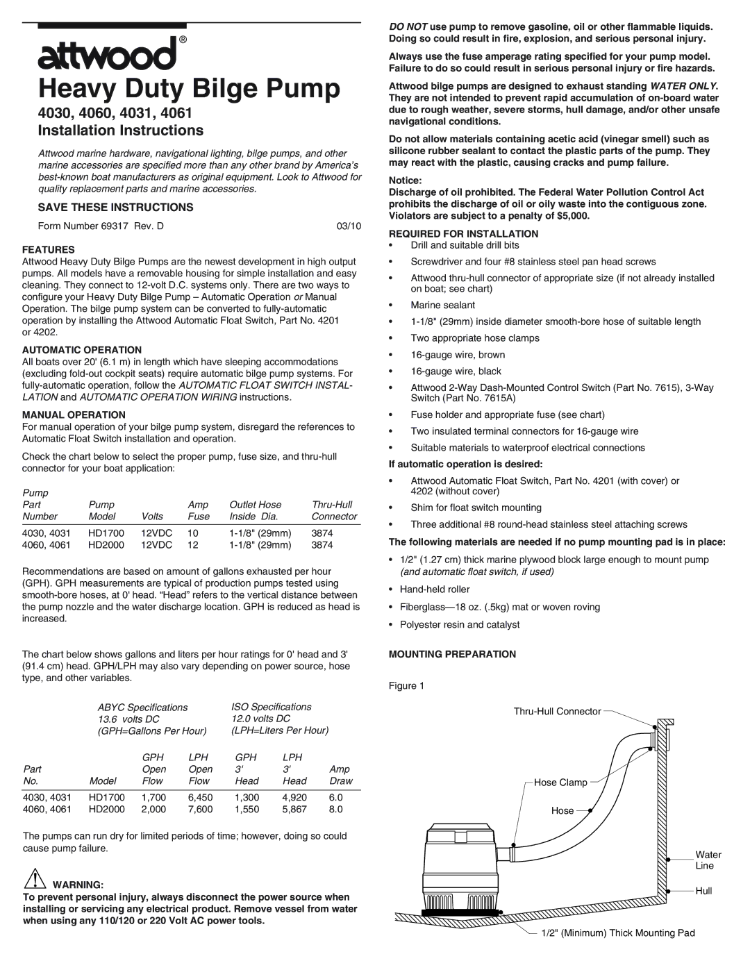
MOUNTING PREPARATION
Figure 1
¥![]()
¥![]()
Hose Clamp
Hose ¥
¥
Water
¥ Line
¥ Hull
![]() ¥
¥
1/2" (Minimum) Thick Mounting Pad