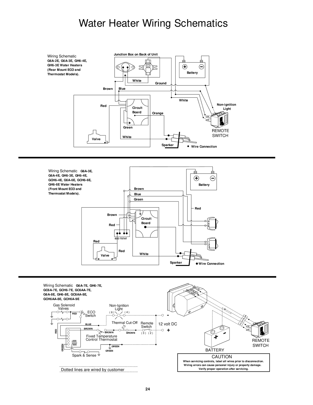
94605 specifications
Atwood Mobile Products 94605 is a robust and reliable solution designed to cater to the needs of RV and trailer enthusiasts. This product has gained considerable attention in the market due to its exceptional build quality, innovative features, and user-friendly design.One of the standout characteristics of the Atwood 94605 is its high efficiency. Designed specifically for recreational vehicles, this product ensures optimal performance, reducing energy consumption while maximizing output. The incorporation of advanced heating technologies allows for quicker heating times and consistent temperature regulation, making it ideal for both short trips and extended outdoor adventures.
The Atwood 94605 is equipped with a lightweight and compact design, allowing for easy installation and integration into various RV models. Its low-profile construction not only minimizes the space it occupies but also enhances its compatibility with numerous vehicle layouts. This careful consideration of design ensures that users can enjoy the benefits of this product without sacrificing space or aesthetic appeal.
Durability is another key feature of the Atwood 94605. Constructed from high-quality materials, this product is built to withstand the rigors of travel and changing weather conditions. This resilience means that users can depend on the Atwood 94605 for years to come, ensuring peace of mind during their adventures.
The ease of use is also a significant aspect of the Atwood 94605. The product boasts straightforward controls that make it accessible for all users, whether they are seasoned RVers or newcomers to the camping experience. The user-friendly interface simplifies the heating process, allowing users to focus on enjoying their trips rather than fussing over complicated systems.
Safety features are paramount in the design of the Atwood 94605. It includes multiple safety mechanisms to prevent overheating and provides users with an added layer of security while in operation. These built-in protections contribute to the overall reliability and trustworthiness of the product.
In conclusion, Atwood Mobile Products 94605 offers an impressive combination of efficiency, durability, and user-friendly operation. With its high-quality construction and advanced heating technology, this product is designed to enhance the RV experience, making it a valuable addition to any outdoor enthusiast's toolkit. Whether embarking on a weekend getaway or a cross-country adventure, the Atwood 94605 is engineered to deliver performance and reliability.

