EM78P312N
8-Bit Microcontroller
| VDD |
|
|
Oscillator | D | Q | CLK |
CLK |
| ||
|
| ||
| CLR |
|
|
|
|
| |
Reset |
|
|
|
Voltage |
|
|
|
Detector |
|
|
|
WDTE |
|
|
|
WDT | WDT Timeout | Setup Time | RESET |
| |||
/RESET |
|
|
|
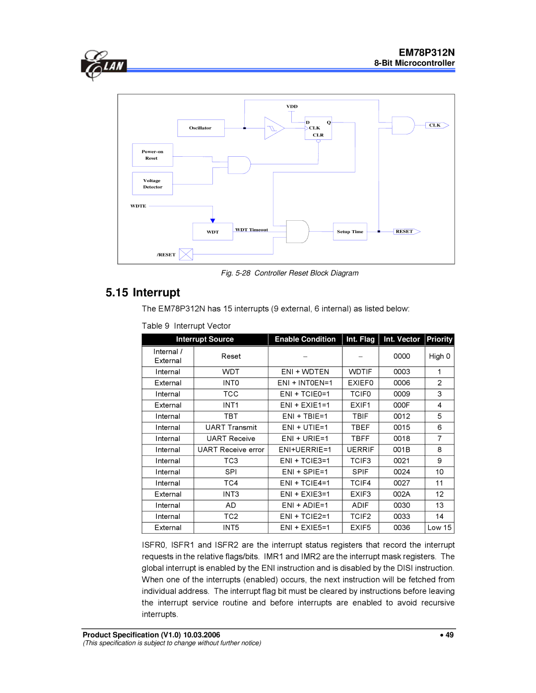
Fig. 5-28 Controller Reset Block Diagram
5.15 Interrupt
The EM78P312N has 15 interrupts (9 external, 6 internal) as listed below:
Table 9 Interrupt Vector
Interrupt Source | Enable Condition | Int. Flag |
Int. Vector Priority
Internal / | Reset | − | − | 0000 | High 0 | |
External | ||||||
|
|
|
|
| ||
Internal | WDT | ENI + WDTEN | WDTIF | 0003 | 1 | |
External | INT0 | ENI + INT0EN=1 | EXIEF0 | 0006 | 2 | |
Internal | TCC | ENI + TCIE0=1 | TCIF0 | 0009 | 3 | |
External | INT1 | ENI + EXIE1=1 | EXIF1 | 000F | 4 | |
Internal | TBT | ENI + TBIE=1 | TBIF | 0012 | 5 | |
Internal | UART Transmit | ENI + UTIE=1 | TBEF | 0015 | 6 | |
Internal | UART Receive | ENI + URIE=1 | TBFF | 0018 | 7 | |
Internal | UART Receive error | ENI+UERRIE=1 | UERRIF | 001B | 8 | |
Internal | TC3 | ENI + TCIE3=1 | TCIF3 | 0021 | 9 | |
Internal | SPI | ENI + SPIE=1 | SPIF | 0024 | 10 | |
|
|
|
|
|
| |
Internal | TC4 | ENI + TCIE4=1 | TCIF4 | 0027 | 11 | |
External | INT3 | ENI + EXIE3=1 | EXIF3 | 002A | 12 | |
|
|
|
|
|
| |
Internal | AD | ENI + ADIE=1 | ADIF | 0030 | 13 | |
Internal | TC2 | ENI + TCIE2=1 | TCIF2 | 0033 | 14 | |
|
|
|
|
|
| |
External | INT5 | ENI + EXIE5=1 | EXIF5 | 0036 | Low 15 | |
|
|
|
|
|
|
ISFR0, ISFR1 and ISFR2 are the interrupt status registers that record the interrupt requests in the relative flags/bits. IMR1 and IMR2 are the interrupt mask registers. The global interrupt is enabled by the ENI instruction and is disabled by the DISI instruction. When one of the interrupts (enabled) occurs, the next instruction will be fetched from individual address. The interrupt flag bit must be cleared by instructions before leaving the interrupt service routine and before interrupts are enabled to avoid recursive interrupts.
Product Specification (V1.0) 10.03.2006 | • 49 |
(This specification is subject to change without further notice)
