EM78P312N
8-Bit Microcontroller
5.4 CPU Operation Mode
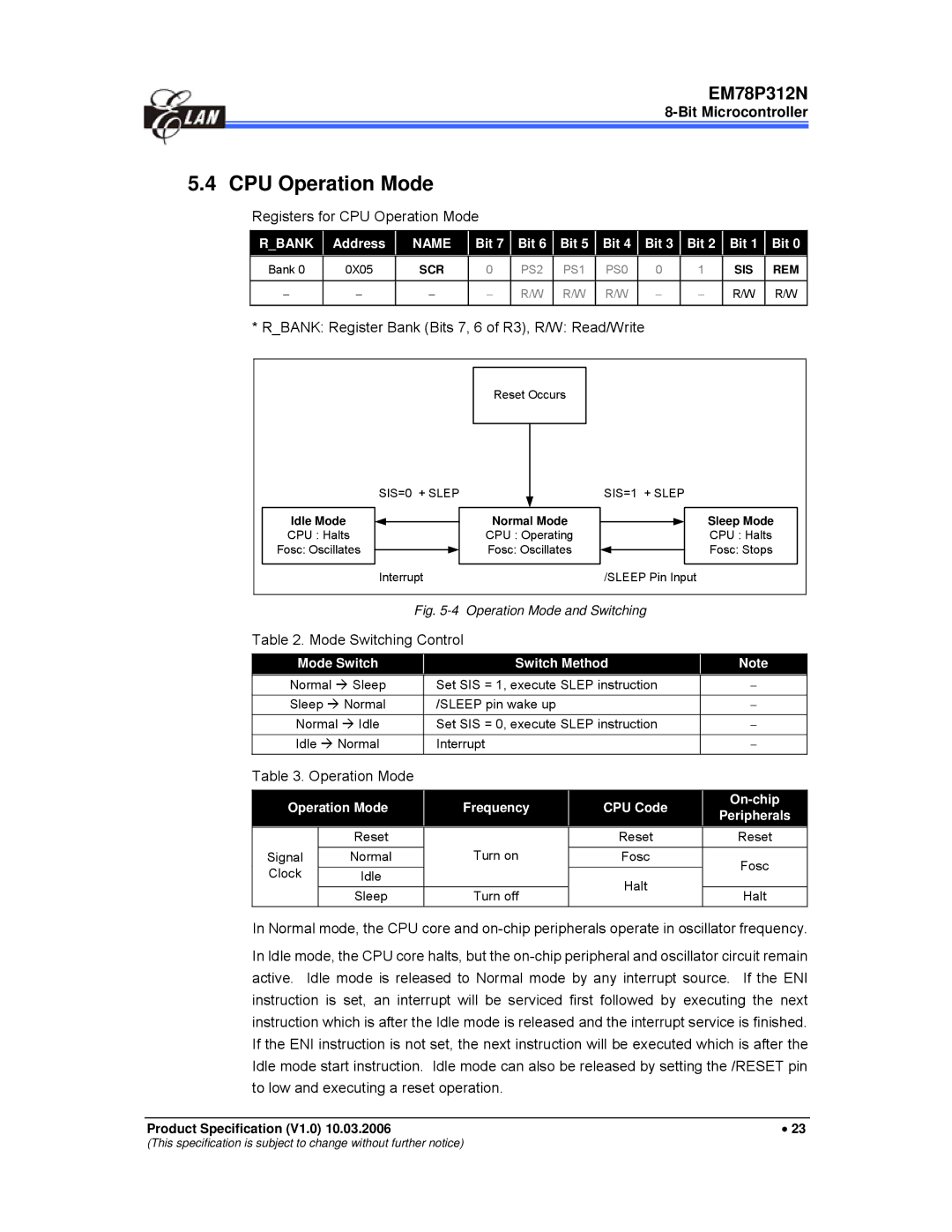
Registers for CPU Operation Mode
R_BANK | Address |
| NAME |
| Bit 7 |
| Bit 6 |
| Bit 5 |
| Bit 4 |
| Bit 3 |
| Bit 2 |
| Bit 1 |
| Bit 0 |
Bank 0 | 0X05 |
| SCR |
| 0 |
| PS2 |
| PS1 |
| PS0 |
| 0 |
| 1 |
| SIS |
| REM |
|
|
|
|
|
|
|
|
|
|
|
|
|
|
|
|
|
|
|
|
− | − |
| − |
| − |
| R/W |
| R/W |
| R/W |
| − |
| − |
| R/W |
| R/W |
|
|
|
|
|
|
|
|
|
|
|
|
|
|
|
|
|
|
|
|
* R_BANK: Register Bank (Bits 7, 6 of R3), R/W: Read/Write | ||
| Reset Occurs |
|
| SIS=0 + SLEP | SIS=1 + SLEP |
Idle Mode | Normal Mode | Sleep Mode |
CPU : Halts | CPU : Operating | CPU : Halts |
Fosc: Oscillates | Fosc: Oscillates | Fosc: Stops |
| Interrupt | /SLEEP Pin Input |
Fig. 5-4 Operation Mode and Switching
Table 2. Mode Switching Control
Mode Switch |
| Switch Method |
| Note |
Normal Æ Sleep |
| Set SIS = 1, execute SLEP instruction |
| − |
Sleep Æ Normal |
| /SLEEP pin wake up |
| − |
Normal Æ Idle |
| Set SIS = 0, execute SLEP instruction |
| − |
Idle Æ Normal |
| Interrupt |
| − |
Table 3. Operation Mode
Operation Mode | Frequency | |
|
|
|
| Reset |
|
Signal | Normal | Turn on |
Clock | Idle |
|
| Sleep | Turn off |
|
|
|
|
| ||
CPU Code | |||
| Peripherals | ||
Reset |
| ||
| Reset | ||
Fosc |
| Fosc | |
|
| ||
Halt |
|
| |
| Halt | ||
|
| ||
|
|
|
In Normal mode, the CPU core and
In Idle mode, the CPU core halts, but the
Product Specification (V1.0) 10.03.2006 | • 23 |
(This specification is subject to change without further notice)
