EM78P312N
8-Bit Microcontroller
5.19 Instruction Set
Each instruction in the instruction set is a
In case the instruction cycle specification is not suitable for certain applications, try to modify the instruction as follows:
(A)Change one instruction cycle to consist of 4 oscillator periods.
(B)The following commands are executed within two instruction cycles; "JMP", "CALL", "RET", "RETL", "RETI", including the conditional skip ("JBS", "JBC", "JZ", "JZA", "DJZ", "DJZA") instructions. In addition, instructions that are written to the program counter are executed within two instruction cycles.
Case (A) is selected by the CODE Option bit, called CLK. One instruction cycle consists of two oscillator clocks if CLK is low, and four oscillator clocks if CLK is high.
Note that once the 4 oscillator periods within one instruction cycle is selected as in Case (A), the internal clock source to TCC should be CLK=Fosc/4, not Fosc/2.
Furthermore, the instruction set has the following features:
(1)Every bit of any register can be set, cleared, or tested directly.
(2)The I/O register can be regarded as general register. That is, the same instruction can operate on I/O register.
Convention:
R = Register designator that specifies which one of the registers (including operation and general purpose registers) is to be utilized by the instruction.
b = Bit field designator that selects the value for the bit located in the register R and which affects the operation.
k = 8 or
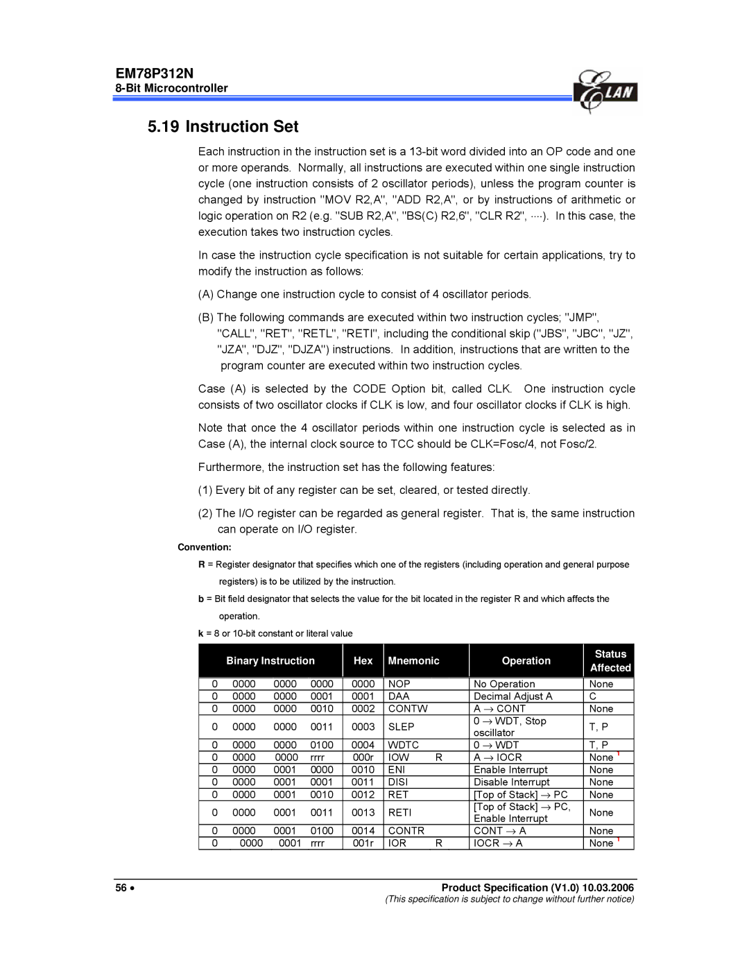
|
| Binary Instruction |
| Hex |
| Mnemonic |
| Operation |
| Status |
|
| |||
|
|
|
|
|
| Affected |
|
| |||||||
|
|
|
|
|
|
|
|
|
|
|
|
|
|
| |
| 0 | 0000 | 0000 | 0000 |
| 0000 |
| NOP |
|
| No Operation | None |
| ||
| 0 | 0000 | 0000 | 0001 |
| 0001 |
| DAA |
|
| Decimal Adjust A | C |
| ||
| 0 | 0000 | 0000 | 0010 |
| 0002 |
| CONTW |
|
| A → CONT | None |
| ||
| 0 | 0000 | 0000 | 0011 |
| 0003 |
| SLEP |
|
| 0 → WDT, Stop | T, P |
| ||
|
|
|
|
| oscillator |
| |||||||||
|
|
|
|
|
|
|
|
|
|
|
|
|
| ||
| 0 | 0000 | 0000 | 0100 |
| 0004 |
| WDTC |
|
| 0 → WDT | T, P |
| ||
| 0 | 0000 | 0000 | rrrr |
| 000r |
| IOW | R |
| A → IOCR | None 1 |
| ||
| 0 | 0000 | 0001 | 0000 |
| 0010 |
| ENI |
|
| Enable Interrupt | None |
| ||
| 0 | 0000 | 0001 | 0001 |
| 0011 |
| DISI |
|
| Disable Interrupt | None |
| ||
| 0 | 0000 | 0001 | 0010 |
| 0012 |
| RET |
|
| [Top of Stack] → PC | None |
| ||
| 0 | 0000 | 0001 | 0011 |
| 0013 |
| RETI |
|
| [Top of Stack] → PC, | None |
| ||
|
|
|
|
| Enable Interrupt |
| |||||||||
|
|
|
|
|
|
|
|
|
|
|
|
|
| ||
| 0 | 0000 | 0001 | 0100 |
| 0014 |
| CONTR |
|
| CONT → A | None |
| ||
| 0 | 0000 | 0001 | rrrr |
| 001r |
| IOR | R |
| IOCR → A | None 1 |
| ||
|
|
|
|
|
|
|
|
|
|
|
|
|
|
|
|
56 • |
|
|
|
|
|
|
| Product Specification (V1.0) 10.03.2006 | |||||||
(This specification is subject to change without further notice)