IBM EM78P312N manual 5.12 TCC/WDT & Prescaler, PWM Mode, Bit Microcontroller

Models: EM78P312N

1 68
Download 68 pages 28.33 Kb
Page 45
Image 45
5.11.4 PWM Mode

EM78P312N

8-Bit Microcontroller

5.11.4 PWM Mode

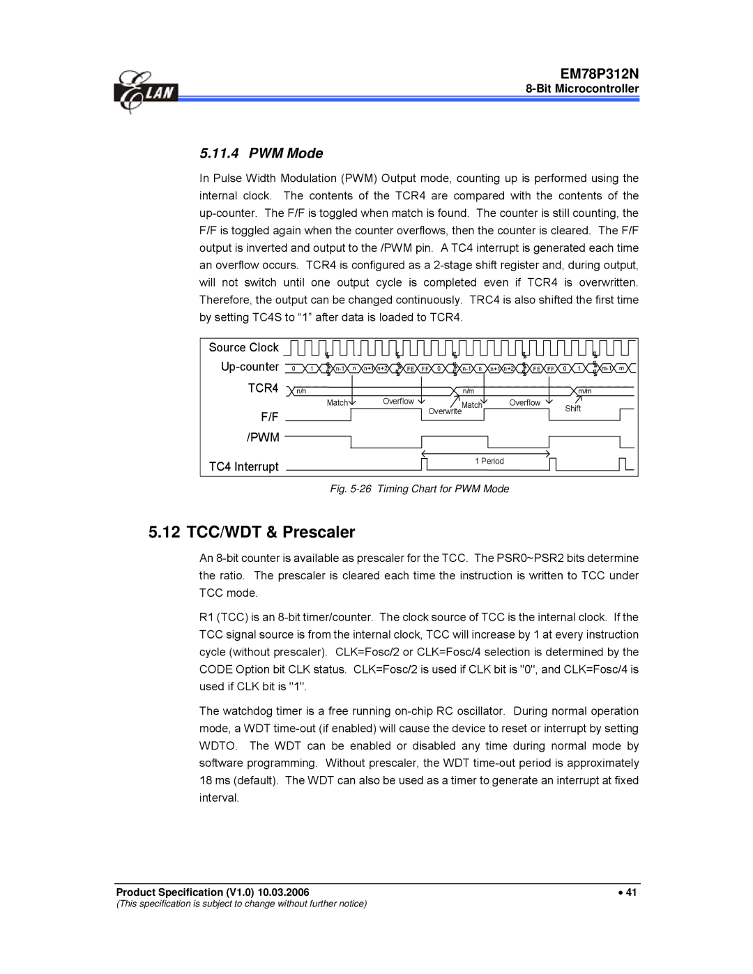
In Pulse Width Modulation (PWM) Output mode, counting up is performed using the internal clock. The contents of the TCR4 are compared with the contents of the up-counter. The F/F is toggled when match is found. The counter is still counting, the F/F is toggled again when the counter overflows, then the counter is cleared. The F/F output is inverted and output to the /PWM pin. A TC4 interrupt is generated each time an overflow occurs. TCR4 is configured as a 2-stage shift register and, during output, will not switch until one output cycle is completed even if TCR4 is overwritten. Therefore, the output can be changed continuously. TRC4 is also shifted the first time by setting TC4S to “1” after data is loaded to TCR4.

Source Clock


Up-counter

0

1

n-1

n

n+1 n+2

FE

FF 0

n-1

n

n+1 n+2

FE

FF

0

1

m-1

m

TCR4


n/n


Overflow


n/m


m/m


Match


Match

Overflow


Shift


F/F


Overwrite


/PWM


TC4 Interrupt


1 Period


Fig. 5-26 Timing Chart for PWM Mode

5.12 TCC/WDT & Prescaler

An 8-bit counter is available as prescaler for the TCC. The PSR0~PSR2 bits determine the ratio. The prescaler is cleared each time the instruction is written to TCC under TCC mode.

R1 (TCC) is an 8-bit timer/counter. The clock source of TCC is the internal clock. If the TCC signal source is from the internal clock, TCC will increase by 1 at every instruction cycle (without prescaler). CLK=Fosc/2 or CLK=Fosc/4 selection is determined by the CODE Option bit CLK status. CLK=Fosc/2 is used if CLK bit is "0", and CLK=Fosc/4 is used if CLK bit is "1".

The watchdog timer is a free running on-chip RC oscillator. During normal operation mode, a WDT time-out (if enabled) will cause the device to reset or interrupt by setting WDTO. The WDT can be enabled or disabled any time during normal mode by software programming. Without prescaler, the WDT time-out period is approximately 18 ms (default). The WDT can also be used as a timer to generate an interrupt at fixed interval.

Product Specification (V1.0) 10.03.2006

41

(This specification is subject to change without further notice)

Page 45
Image 45
IBM EM78P312N manual 5.12 TCC/WDT & Prescaler, PWM Mode, Bit Microcontroller