LITERATURE NUMBER MPD 85810

9

TELESCOPING STABILIZER

ENGLISH

•Installation •Operation •Maintenance


Effective 11/21/07

SAFETY ALERT SYMBOLS

Safety Symbols alert you to potential personal safety hazards. Obey all safety messages following these symbols.

￿WARNING

￿CAUTION

avoid possible

avoid possible

injury or death

injury and/or property damage

For your safety read all instructions before operating landing legs.

Installer: Provide these instructions to the consumer.

Consumer: Keep documents for future reference.

DO NOT EXCEED CAPACITY

STABILIZER

2˝ SQUARE

2.5˝ SQUARE

MAXIMUM VERTICAL LOAD

3,000 LB.

6,000 LB.

3.Assemble drop tube (FIG 1-B) to 2.5˝ square housing (FIG 1-A) in a fully retracted position using lock pin (FIG 1-G). For 2˝ square, assemble drop tube to housing with the ball detent pin (FIG 1-F). Mount footpad with its length running from front to rear of the trailer.

NOTE: Optional spring-loaded pull pins (FIG 2-A Pull Pin or FIG 2-B on the 2.5˝ square stabilizer “SNAPSTM”) are available to replace FIG 1- G or F respectively. There must be a half-hole at the bottom of the housing in order to use the pull pin. If using a pull-pin, assemble it to the housing per its instruction manual.

OPERATION

￿WARNING

MOVING PARTS CAN CRUSH OR CUT OR PINCH POINT

• Keep hands and clothing away from moving parts.

￿WARNING

TRAILER CAN MOVE OR COLLAPSE

Never exceed the rated capacity.

STABILIZERS ARE NOT DESIGNED TO BE USED AS TRAILER JACKS. Do not use

the stabilizer to lift or support the trailer during tire changes, axle work or trailer servicing (the trailer weight will exceed the capacity of the stabilizer). The stabilizer is designed to stabilize a portion of the trailer’s weight. Support the front end of the trailer with structur- al stands rated for the GVWR of the trailer.

The pin between the housing and drop tube should be the same diameter as the adjustment hole in the drop tube. Otherwise prema- ture wear on drop tube and housing can occur.

INSTALLATION

￿CAUTION

HAZARDOUS FUMES

Adequate ventilation must be provided when welding.

WELDING INSTRUCTIONS

M.I.G. OR STICK - Attach with 3/16˝ fillet weld minimum.

M.I.G. WELDING - Use A.W.S. ER 70S-3 or 6 wire or equivalent with a diameter of .035 - .045. The recommended shielding gas mixture is 75% - 95% Argon & 25% - 5% CO2.

STICK WELDING - Use E6011 A.W.S. welding rod or equivalent. Recommended machine settings for specific electrode diameters are as follows: 1/8˝ electrode set power between 115-130 Amps DC or 5/32” electrode set power between 140-160 Amps DC.

1.Weld two sides of housing to structural attachment point on trailer surface (FIG 3-A, 4-A & 4-B). Use a minimum of 4˝ of 3/16˝ fillet lin- ear weld total on each side, stich or continuous (FIG 4-A & B). See welding instructions. When locating housing on trailer make sure access for lock pin is available for easy adjustment.

2.Assemble foot pad (FIG 1-D) to drop tube (FIG 1-B) with bridge pin clip (FIG 1-C) and clevis pin (FIG 1-E) for 2.5˝ square stabilizer.

￿WARNING

TRAILER CAN MOVE OR COLLAPSE

Never exceed rated capacity of stabilizer.

STABILIZERS ARE NOT DESIGNED TO BE USED AS TRAILER JACKS. Do not use the

stabilizer to lift or support the trailer during tire changes, axle work or trailer servicing (the trailer weight will exceed the capacity of the stabilizer). The stabilizer is designed to stabilize a portion of the trail- er’s weight. Support the front end of the trailer with structural stands rated for the GVWR of the trailer.

Chock both sides of trailer wheels before operating stabilizer.

All legs must touch the ground or the surface at the same time.

Retract stabilizer completely before towing trailer.

￿CAUTION

SECURE TRAILER BEFORE TRAVELING

Before retracting, ensure there is no load on the stabilizer. Securely latch hitch before retracting stabilizer.

Lock pin spring clip must be positioned around stabilizer and secured over end of pin on opposite side of housing tube. This pre- vents pin from coming out during travel (FIG 1-G).

FOR 2.0˝ STABILIZER insure the ball detent pin is fully extended through the leg (FIG 1-F).

TO EXTEND THE STABILIZER - Remove the pin in the drop tube or, if you have a pull pin that doesn’t remove, pull the handle pin so the pin is disengaged. Let the drop tube fall to the ground and re-pin in the nearest adjustment hole.

TO RETRACT STABILIZER - Make sure there is no load on the stabiliz- er. Remove pin or disengage the pull pin and raise the drop tube, re- pinning it in the highest position. Fully retract the legs so that the foot pad is higher than the lowest point of the trailer, to prevent dragging while going over a curb.

Before towing, check for maximum clearance between ground and bot- tom of stabilizer.

1

Page 1
Image 1
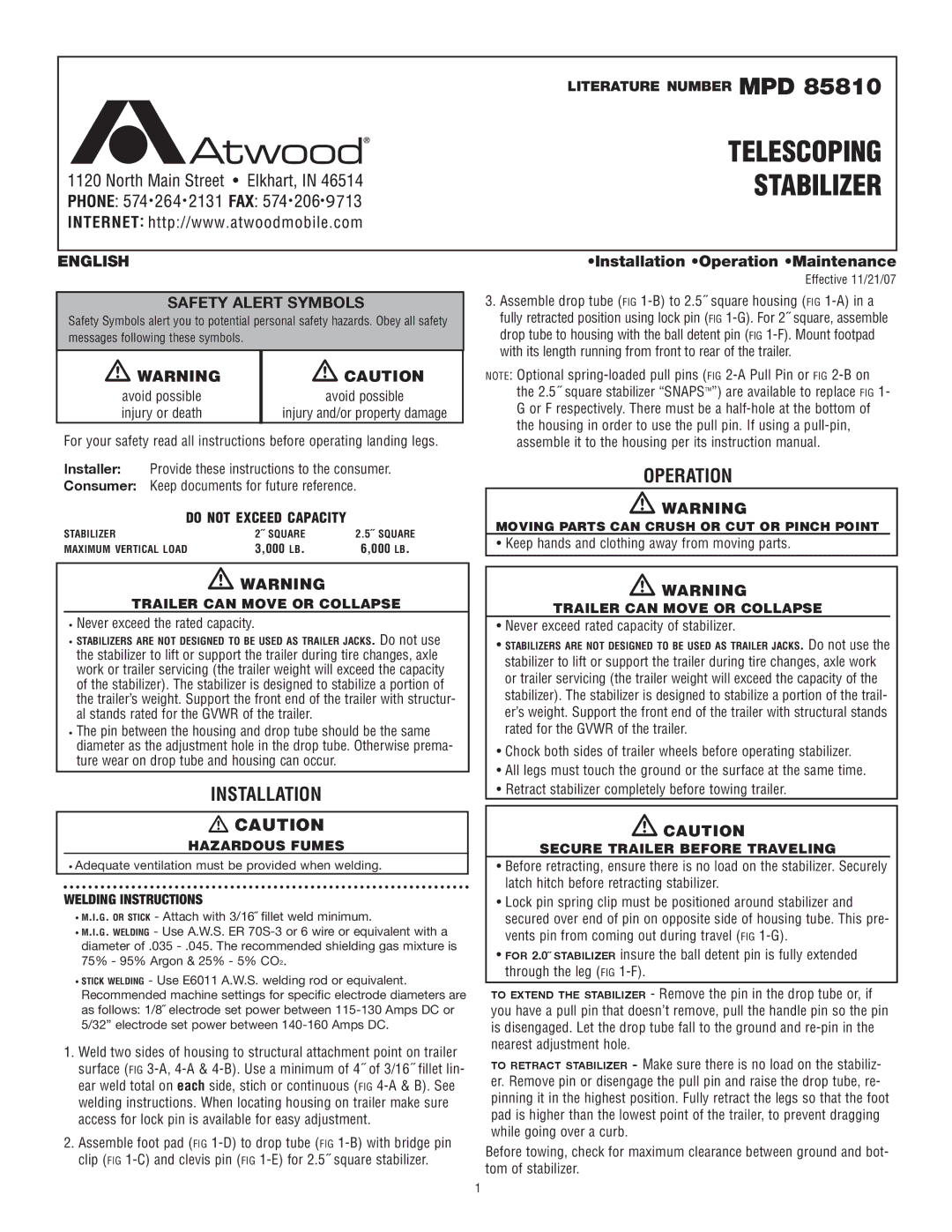
Atwood Mobile Products MPD 85810 instruction manual Operation, Installation

MPD 85810 specifications

The Atwood Mobile Products MPD 85810 is a top-tier mobile product designed specifically for the modern camper or outdoor enthusiast. This innovative product combines practicality with state-of-the-art technology, making it an ideal choice for those looking to enhance their outdoor experiences.

One of the standout features of the MPD 85810 is its robust design. Crafted from high-quality materials, it is built to withstand the rigors of outdoor use while remaining lightweight and portable. The durable construction ensures longevity, allowing users to rely on it for countless adventures.

The MPD 85810 incorporates advanced heating technology, providing efficient and effective heating solutions. It is designed with a powerful heating element that ensures rapid warmth, making it perfect for chilly nights in the great outdoors. This element is complemented by a safety shut-off feature, which adds an extra layer of security by preventing overheating.

Another impressive aspect of the Atwood Mobile Products MPD 85810 is its ease of installation. The product comes with a straightforward instructional guide, enabling users to set it up quickly without the need for professional assistance. This user-friendly approach means that even those new to camping or mobile products can use it competently.

In terms of versatility, the MPD 85810 shines with its multiple applications. Whether you’re camping in an RV, traveling in a trailer, or enjoying a tailgate party, this product adapts to your needs seamlessly. Its compact design makes it easy to store and transport, ensuring it fits into any setup without taking up excessive space.

Additionally, the MPD 85810 boasts energy efficiency, making it an eco-friendly choice for outdoor activities. It is designed to use minimal power while providing maximum output, allowing users to conserve battery life or fuel.

In conclusion, the Atwood Mobile Products MPD 85810 stands out in the realm of mobile camping products due to its robust construction, advanced heating technology, user-friendly installation, versatility, and energy efficiency. Whether you're an avid camper or a casual weekend warrior, the MPD 85810 is engineered to enhance your outdoor experience, making it a valuable addition to your camping gear. As outdoor adventures continue to gain popularity, products like the MPD 85810 will undoubtedly remain in high demand for their reliability and performance.