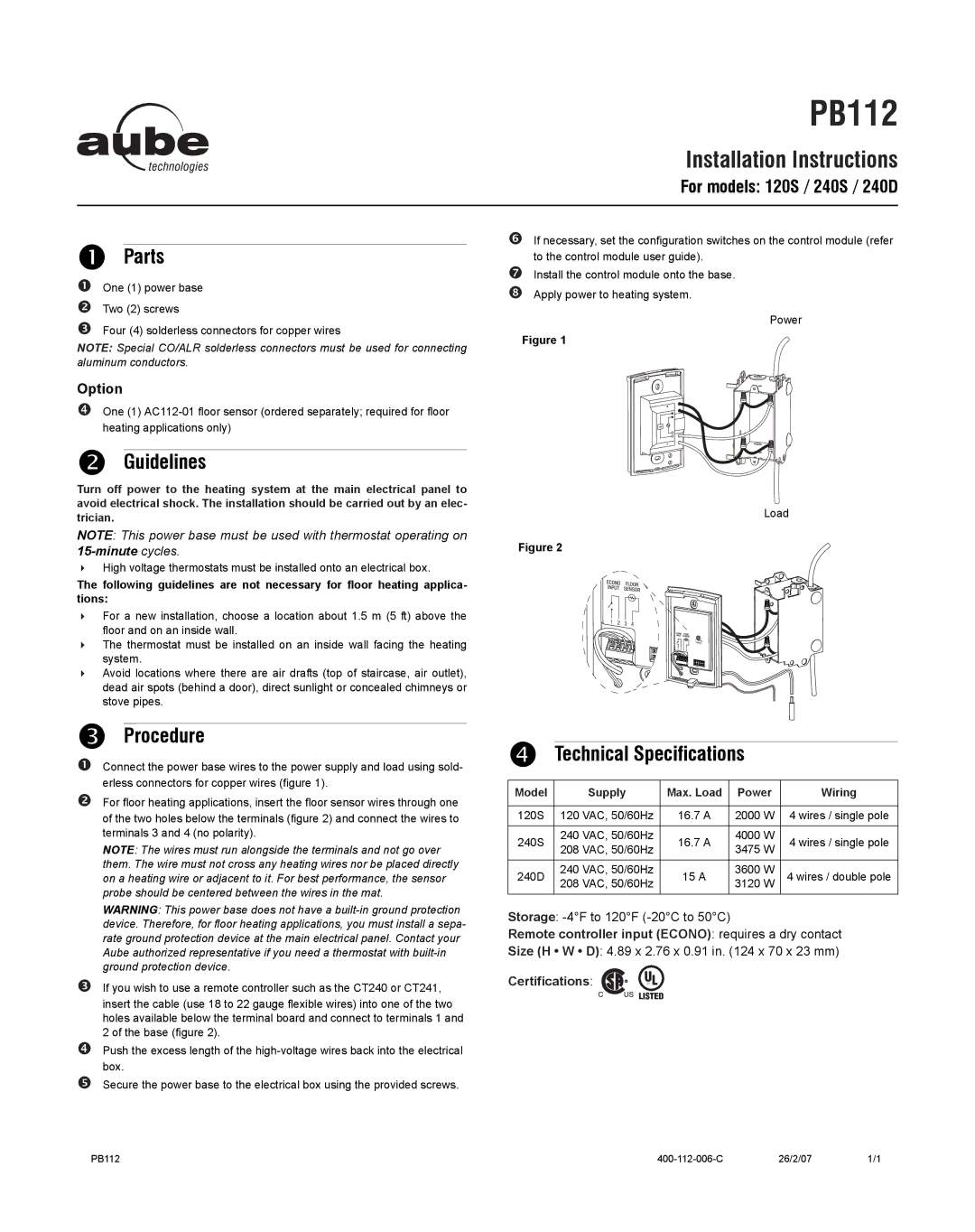
TH115 specifications
Aube Technologies TH115 is a state-of-the-art digital thermostat designed specifically for electric heating systems. With its sleek and modern design, the TH115 seamlessly integrates into any home setting, providing efficient and user-friendly temperature control. This device is ideal for homeowners seeking a reliable solution for managing their heating, ensuring comfort while maintaining energy efficiency.One of the standout features of the TH115 is its intuitive interface, which includes a large, backlit display. This allows users to easily read and adjust the settings, even in low-light conditions. The thermostat offers a straightforward programming system, allowing users to set customized schedules for heating based on their daily routines. With the ability to create specific timeframes for weekdays and weekends, users can significantly enhance their comfort while optimizing energy use.
The TH115 employs advanced technologies to ensure precise temperature management. It includes an adaptive ramp-up feature that allows the thermostat to adjust the heating gradually, preventing abrupt temperature changes and enhancing overall comfort. The device also utilizes a built-in temperature sensor that monitors the ambient temperature continuously, allowing for real-time adjustments to maintain the desired comfort level.
Another notable characteristic of the TH115 is its energy-saving capabilities. The thermostat is designed to minimize energy consumption by automatically switching to an energy-saving mode when occupants are away, reducing unnecessary heating costs. Additionally, users can take advantage of the unit's vacation mode, which allows them to set a lower temperature during extended absences, further contributing to energy savings.
The TH115 is compatible with various electric heating systems, including baseboard heaters and radiant floor heating. This versatility makes it suitable for a wide range of installations, allowing users to benefit from its features regardless of their specific heating setup. Furthermore, the thermostat is easy to install, making it accessible even for those with minimal technical knowledge.
In conclusion, the Aube Technologies TH115 digital thermostat offers a combination of advanced features, user-friendly design, and energy efficiency, making it an excellent choice for homeowners looking to optimize their heating systems. Its programmable settings, adaptive features, and compatibility with various electric heating solutions distinguish it in the market, ensuring that users can enjoy a comfortable living environment while also reducing their energy footprint.

