Assembling the Turntable Platter and Slip Mat
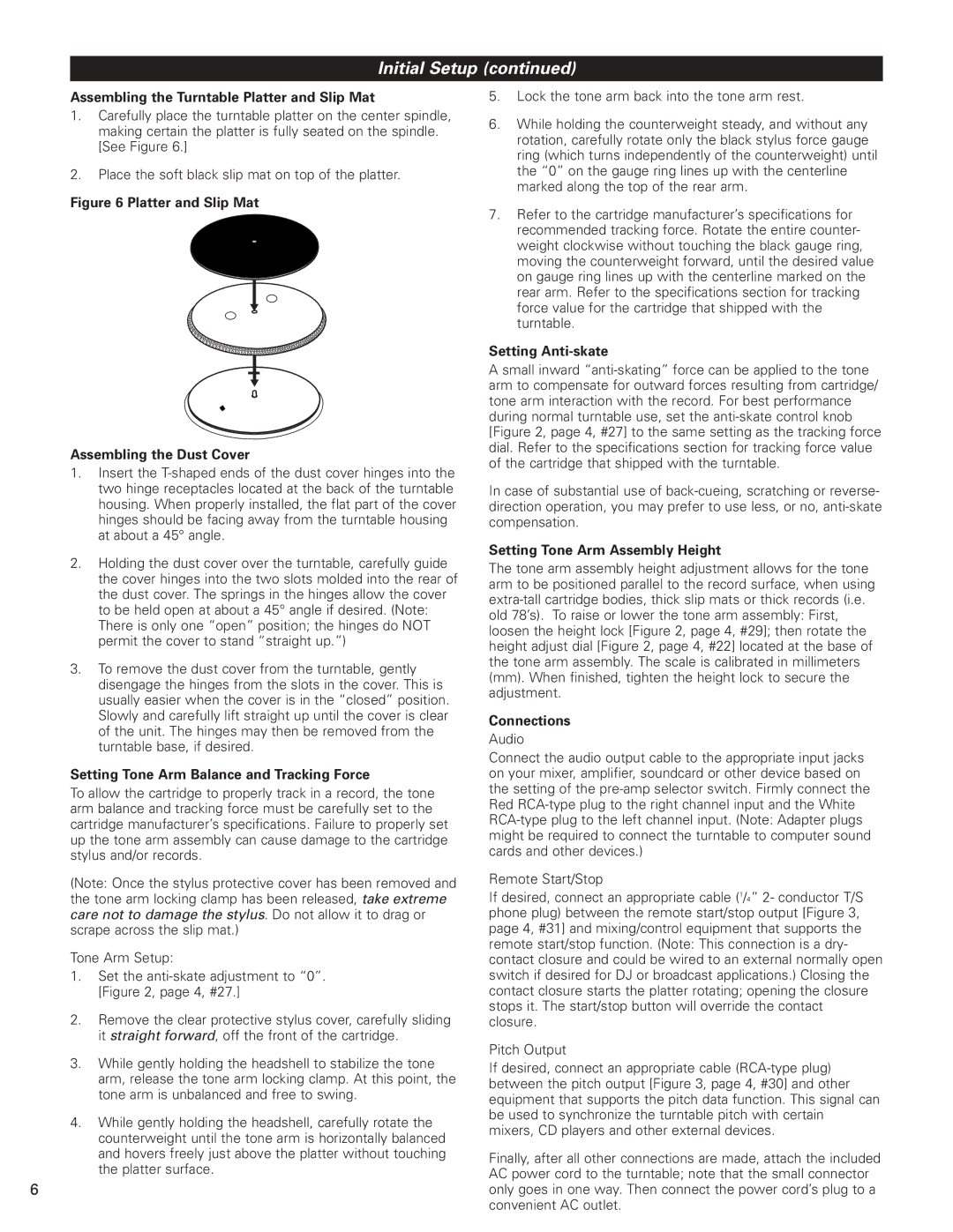
1.Carefully place the turntable platter on the center spindle, making certain the platter is fully seated on the spindle. [See Figure 6.]
2.Place the soft black slip mat on top of the platter.
Figure 6 Platter and Slip Mat
Assembling the Dust Cover
1.Insert the T-shaped ends of the dust cover hinges into the two hinge receptacles located at the back of the turntable housing. When properly installed, the flat part of the cover hinges should be facing away from the turntable housing at about a 45° angle.
2.Holding the dust cover over the turntable, carefully guide the cover hinges into the two slots molded into the rear of the dust cover. The springs in the hinges allow the cover to be held open at about a 45° angle if desired. (Note: There is only one “open” position; the hinges do NOT permit the cover to stand “straight up.”)
3.To remove the dust cover from the turntable, gently disengage the hinges from the slots in the cover. This is usually easier when the cover is in the “closed” position. Slowly and carefully lift straight up until the cover is clear of the unit. The hinges may then be removed from the turntable base, if desired.
Setting Tone Arm Balance and Tracking Force
To allow the cartridge to properly track in a record, the tone arm balance and tracking force must be carefully set to the cartridge manufacturer’s specifications. Failure to properly set up the tone arm assembly can cause damage to the cartridge stylus and/or records.
(Note: Once the stylus protective cover has been removed and the tone arm locking clamp has been released, take extreme care not to damage the stylus. Do not allow it to drag or scrape across the slip mat.)
Tone Arm Setup:
1.Set the anti-skate adjustment to “0”. [Figure 2, page 4, #27.]
2.Remove the clear protective stylus cover, carefully sliding it straight forward, off the front of the cartridge.
3.While gently holding the headshell to stabilize the tone arm, release the tone arm locking clamp. At this point, the tone arm is unbalanced and free to swing.
4.While gently holding the headshell, carefully rotate the counterweight until the tone arm is horizontally balanced and hovers freely just above the platter without touching the platter surface.
6
5.Lock the tone arm back into the tone arm rest.
6.While holding the counterweight steady, and without any rotation, carefully rotate only the black stylus force gauge ring (which turns independently of the counterweight) until the “0” on the gauge ring lines up with the centerline marked along the top of the rear arm.
7.Refer to the cartridge manufacturer’s specifications for recommended tracking force. Rotate the entire counter- weight clockwise without touching the black gauge ring, moving the counterweight forward, until the desired value on gauge ring lines up with the centerline marked on the rear arm. Refer to the specifications section for tracking force value for the cartridge that shipped with the turntable.
Setting Anti-skate
A small inward “anti-skating” force can be applied to the tone arm to compensate for outward forces resulting from cartridge/ tone arm interaction with the record. For best performance during normal turntable use, set the anti-skate control knob [Figure 2, page 4, #27] to the same setting as the tracking force dial. Refer to the specifications section for tracking force value of the cartridge that shipped with the turntable.
In case of substantial use of back-cueing, scratching or reverse- direction operation, you may prefer to use less, or no, anti-skate compensation.
Setting Tone Arm Assembly Height
The tone arm assembly height adjustment allows for the tone arm to be positioned parallel to the record surface, when using extra-tall cartridge bodies, thick slip mats or thick records (i.e. old 78’s). To raise or lower the tone arm assembly: First, loosen the height lock [Figure 2, page 4, #29]; then rotate the height adjust dial [Figure 2, page 4, #22] located at the base of the tone arm assembly. The scale is calibrated in millimeters (mm). When finished, tighten the height lock to secure the adjustment.
Connections
Audio
Connect the audio output cable to the appropriate input jacks on your mixer, amplifier, soundcard or other device based on the setting of the pre-amp selector switch. Firmly connect the Red RCA-type plug to the right channel input and the White RCA-type plug to the left channel input. (Note: Adapter plugs might be required to connect the turntable to computer sound cards and other devices.)
Remote Start/Stop
If desired, connect an appropriate cable (1/4” 2- conductor T/S phone plug) between the remote start/stop output [Figure 3, page 4, #31] and mixing/control equipment that supports the remote start/stop function. (Note: This connection is a dry- contact closure and could be wired to an external normally open switch if desired for DJ or broadcast applications.) Closing the contact closure starts the platter rotating; opening the closure stops it. The start/stop button will override the contact closure.
Pitch Output
If desired, connect an appropriate cable (RCA-type plug) between the pitch output [Figure 3, page 4, #30] and other equipment that supports the pitch data function. This signal can be used to synchronize the turntable pitch with certain mixers, CD players and other external devices.
Finally, after all other connections are made, attach the included AC power cord to the turntable; note that the small connector only goes in one way. Then connect the power cord’s plug to a convenient AC outlet.