6
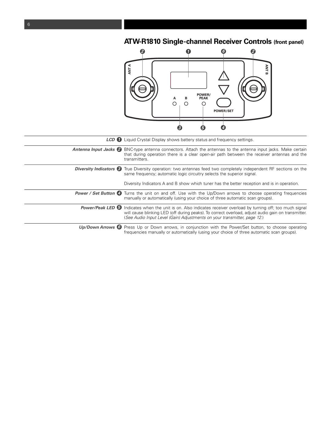
ATW-R1810 Single-channel Receiver Controls (front panel)
2 |
|
| 1 | 6 |
|
| 2 |
| ||||||
|
|
|
|
|
|
|
|
|
|
|
|
|
|
|
|
|
|
|
|
|
|
|
|
|
|
|
|
|
|
|
|
|
|
|
|
|
|
|
|
|
|
|
|
|
|
|
|
|
|
|
|
|
|
|
|
|
|
|
|
|
| 3 | 5 | 4 |
|
|
|
|
| ||
LCD | 1 | Liquid Crystal Display shows battery status and frequency settings. | |||
|
|
|
| ||
Antenna Input Jacks | 2 | ||||
|
| that during operation there is a clear | |||
|
| transmitters. |
|
|
|
|
|
|
| ||
Diversity Indicators | 3 | True Diversity operation: two antennas feed two completely independent RF sections on the | |||
|
| same frequency; automatic logic circuitry selects the superior signal. | |||
|
| Diversity Indicators A and B show which tuner has the better reception and is in operation. | |||
|
|
|
| ||
Power / Set Button | 4 | Turns the unit on and off. Use with the Up/Down arrows to choose operating frequencies | |||
|
| manually or automatically (using your choice of three automatic scan groups). | |||
|
|
|
| ||
Power/Peak LED | 5 | Indicates when the unit is on. Also indicates receiver overload by turning off; too much signal | |||
|
| will cause blinking LED (off during peaks). To correct overload, adjust audio gain on transmitter. | |||
|
| (See Audio Input Level (Gain) Adjustments on your transmitter, page 12.) | |||
|
|
| |||
Up/Down Arrows 6 | Press Up or Down arrows, in conjunction with the Power/Set button, to choose operating | ||||
|
| frequencies manually or automatically (using your choice of three automatic scan groups). | |||