7
(rear panel)
7
10 | 8 | 9 | 11 |
|
| PIN 1 |
| PIN 3 |
|
|
|
|
|
| |||
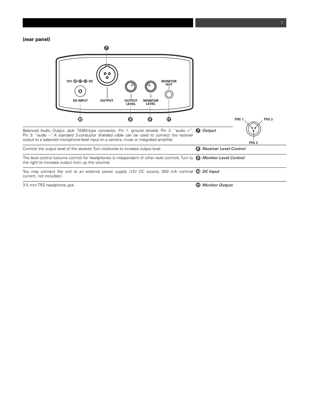
Balanced Audio Output Jack: | 7 | Output |
|
| ||||
|
| |||||||
Pin 3: “audio |
|
|
|
|
| |||
output to a balanced |
|
|
|
|
| |||
|
|
| PIN 2 | |||||
|
|
|
|
|
|
| ||
Controls the output level of the receiver.Turnclockwiseto increase output level. |
| 8 | Receiver Level Control |
|
| |||
|
|
|
|
| ||||
The level control (volume control) for headphones is independent of other level controls. Turn to | 9 | Monitor Level Control |
|
| ||||
the right to increase output (turn up the volume). |
|
|
|
|
|
|
|
|
|
|
|
|
| ||||
You may connect the unit to an external power supply (12V DC source, 500 mA nominal | 10 | DC Input |
|
| ||||
current, not included.) |
|
|
|
|
|
|
|
|
|
|
|
|
|
|
|
| |
3.5 mm TRS headphone jack. |
|
|
| 11 | Monitor Output |
|
| |