Receiver Installation
Location
For best operation the receiver should be at least 3 ft. (1 m) above the ground and at least 3 ft. away from a wall or metal surface to minimize reflections. The transmitter should be at least 3 ft. from the receiver, as shown in Figure A. Keep antennas away from noise sources such as digital equipment, motors, automobiles and neon lights, as well as away from large metal objects.
Figure A
Output Connections
There are two audio outputs on the back panel: balanced
Antennas
Extend the permanently attached UHF antennas. The antennas are normally positioned in the shape of a “V” (both 45° from vertical) for best reception. Diversity Indicators on the receiver front panel will indicate which antenna is active.
Power Connections
Connect the DC plug on the included AC power adapter to the DC power input on the back of the receiver. Secure the cord over the cord hook on the back of the receiver, to keep the plug from being detached by an accidental tug on the cord. Then plug the adapter into a standard 120 Volt 60 Hz AC power outlet.
Receiver Controls and Functions
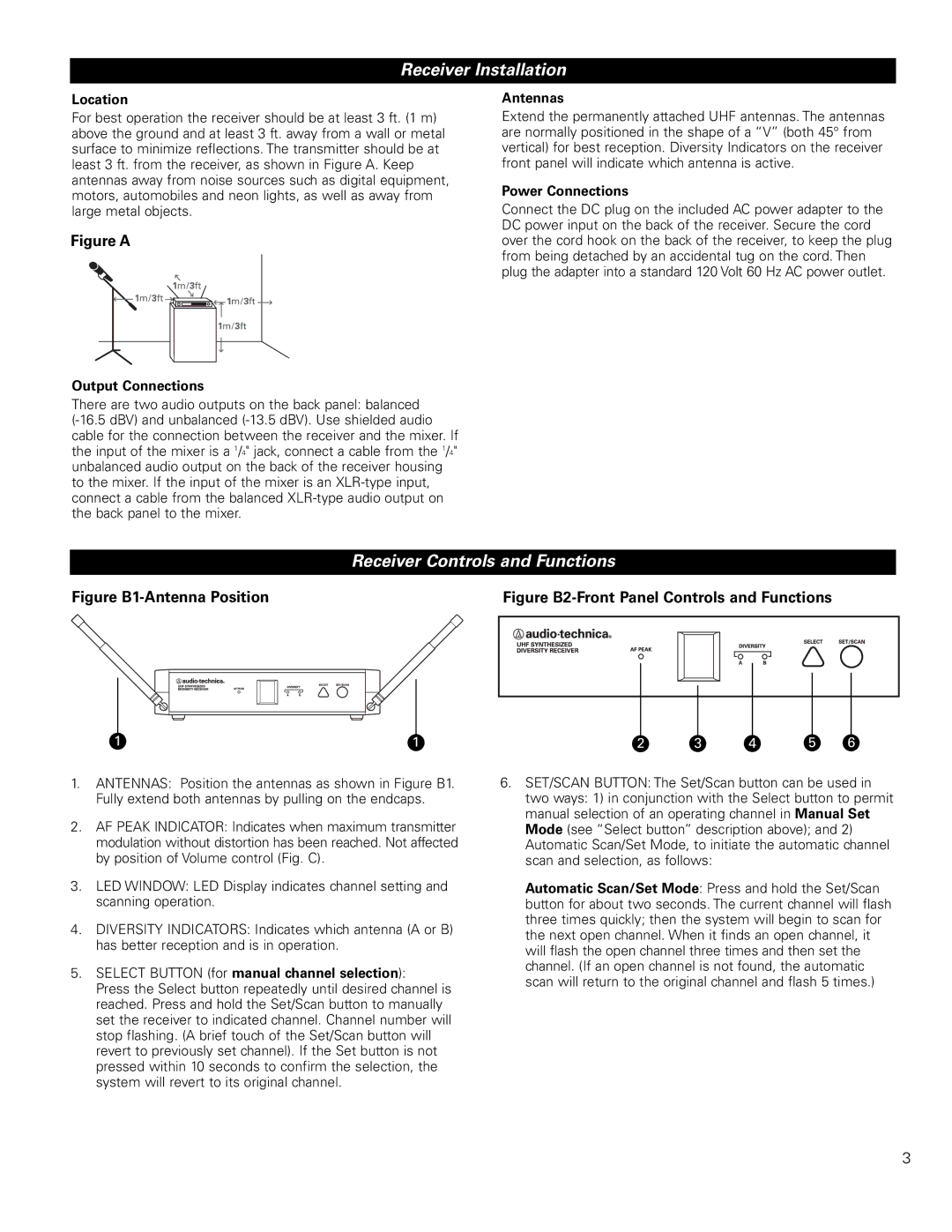
Figure |
| Figure | ||||||
|
|
|
|
|
|
|
|
|
|
|
|
|
|
|
|
|
|
|
|
|
|
|
|
|
|
|
|
|
|
|
|
|
|
|
|
|
|
|
|
|
|
|
|
|
|
|
|
|
|
|
|
|
|
|
|
|
|
|
|
|
|
|
1 | 1 | 2 | 3 | 4 | 5 | 6 |
1.ANTENNAS: Position the antennas as shown in Figure B1. Fully extend both antennas by pulling on the endcaps.
2.AF PEAK INDICATOR: Indicates when maximum transmitter modulation without distortion has been reached. Not affected by position of Volume control (Fig. C).
3.LED WINDOW: LED Display indicates channel setting and scanning operation.
4.DIVERSITY INDICATORS: Indicates which antenna (A or B) has better reception and is in operation.
5.SELECT BUTTON (for manual channel selection):
Press the Select button repeatedly until desired channel is reached. Press and hold the Set/Scan button to manually set the receiver to indicated channel. Channel number will stop flashing. (A brief touch of the Set/Scan button will revert to previously set channel). If the Set button is not pressed within 10 seconds to confirm the selection, the system will revert to its original channel.
6.SET/SCAN BUTTON: The Set/Scan button can be used in
two ways: 1) in conjunction with the Select button to permit manual selection of an operating channel in Manual Set Mode (see “Select button” description above); and 2) Automatic Scan/Set Mode, to initiate the automatic channel scan and selection, as follows:
Automatic Scan/Set Mode: Press and hold the Set/Scan button for about two seconds. The current channel will flash three times quickly; then the system will begin to scan for the next open channel. When it finds an open channel, it will flash the open channel three times and then set the channel. (If an open channel is not found, the automatic scan will return to the original channel and flash 5 times.)
3