Receiver Controls and Functions (Continued)
Figure C-Rear Panel Controls and Functions
8 | 9 | 10 | 11 | 12 |
8.UNBALANCED AUDIO OUTPUT JACK: 1/4" phone jack. Can be connected to an unbalanced
9.AF LEVEL (VOLUME) CONTROL: Adjusts audio output level of both AF Output jacks; maximum output is fully clockwise.
10.BALANCED AUDIO OUTPUT JACK:
11.CORD HOOK: Loop the cord around the cord hook to keep the DC plug from pulling out accidentally.
12.POWER INPUT JACK:Connect the DC plug from the included
Transmitter Setup, Controls and Functions
Battery Selection
Two 1.5VAA alkaline batteries are recommended.
UniPak® Transmitter Battery Installation
1.Open the transmitter door by first pulling the catch down and then sliding the door upward (Fig. D).
2.Observe correct polarity as marked and carefully insert two fresh 1.5V AA alkaline batteries (Fig. D).
3.Slide the door closed, making certain it clicks securely in place.
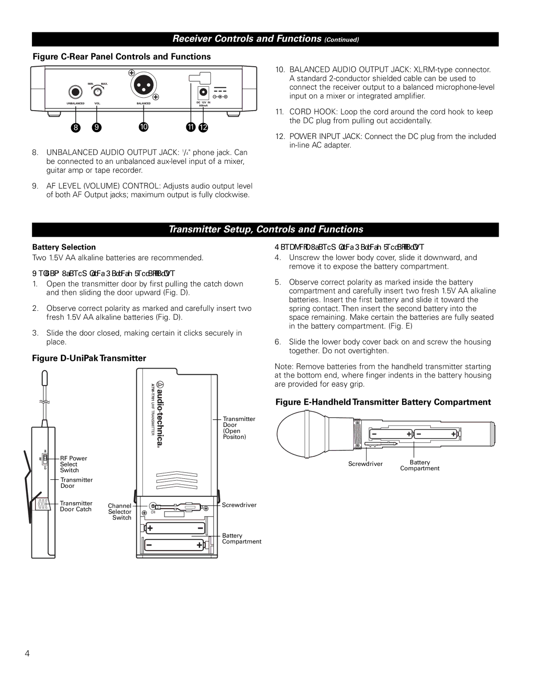
Figure D-UniPak Transmitter
|
| Transmitter |
|
| Door |
|
| (Open |
|
| Positon) |
RF Power |
|
|
Select |
|
|
Switch |
|
|
Transmitter |
|
|
Door |
|
|
Transmitter | Channel | Screwdriver |
Door Catch | Selector |
|
| Switch |
|
|
| Battery |
|
| Compartment |
HandheldTransmitter Battery Installation
4.Unscrew the lower body cover, slide it downward, and remove it to expose the battery compartment.
5.Observe correct polarity as marked inside the battery compartment and carefully insert two fresh 1.5V AA alkaline batteries. Insert the first battery and slide it toward the spring contact. Then insert the second battery into the space remaining. Make certain the batteries are fully seated in the battery compartment. (Fig. E)
6.Slide the lower body cover back on and screw the housing together. Do not overtighten.
Note: Remove batteries from the handheld transmitter starting at the bottom end, where finger indents in the battery housing are provided for easy grip.
Figure E-Handheld Transmitter Battery Compartment
Screwdriver Battery
Compartment
4