AMP110, Home Audio Multi-Zone Power Amplier, AMP102 specifications
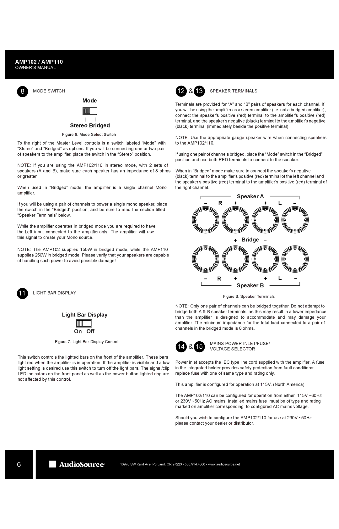
The AudioSource AMP102 and AMP110 are exceptional home audio multi-zone power amplifiers designed to elevate your audio experience. Catering to music enthusiasts and professionals alike, these amplifiers provide extensive power and flexibility to suit various audio needs.The AMP102 is a two-channel amplifier rated at 100 watts per channel, whereas the AMP110 boasts a significant enhancement with 110 watts per channel. Both models are engineered to drive a variety of speaker configurations, making them perfect for multi-room setups. With the ability to connect up to four separate pairs of speakers, these amplifiers ensure that you can fill your entire home with high-quality sound.
One of the standout features of the AudioSource amplifiers is their robust construction and efficient design. They utilize advanced technologies to provide clean and powerful audio reproduction, characterized by low total harmonic distortion (THD). This ensures that listeners enjoy a crisp, clear audio experience without unwanted artifacts or noise.
Both amplifiers support multiple input options, including RCA and 1/4-inch TRS inputs, allowing for seamless connectivity to various audio sources such as TVs, CD players, and streaming devices. The rear-panel input selection switch makes it easy to switch between different sources, providing added convenience for users.
The multi-zone functionality of the AMP102 and AMP110 is particularly noteworthy. Users can enjoy independent audio control in different rooms, allowing for personalized listening experiences across various spaces in the home. Each zone can be adjusted for volume independently, ensuring everyone can enjoy their preferred audio without disturbing others.
For those who value energy efficiency, both models comply with Energy Star standards, making them environmentally friendly choices. They also come with built-in protection circuitry to safeguard against short circuits, overheating, and speaker overload, prolonging the lifespan of the amplifier.
In summary, the AudioSource AMP102 and AMP110 are versatile and powerful audio amplifiers that bring high-quality sound to any home. With their multi-zone capabilities, flexible connectivity options, and robust design, they are an excellent choice for any audio setup, ensuring that users can enjoy their favorite music in any area of their home with clarity and precision. Whether you are hosting a gathering or simply enjoying a quiet evening, these amplifiers deliver an enriching audio experience that enhances any environment.

