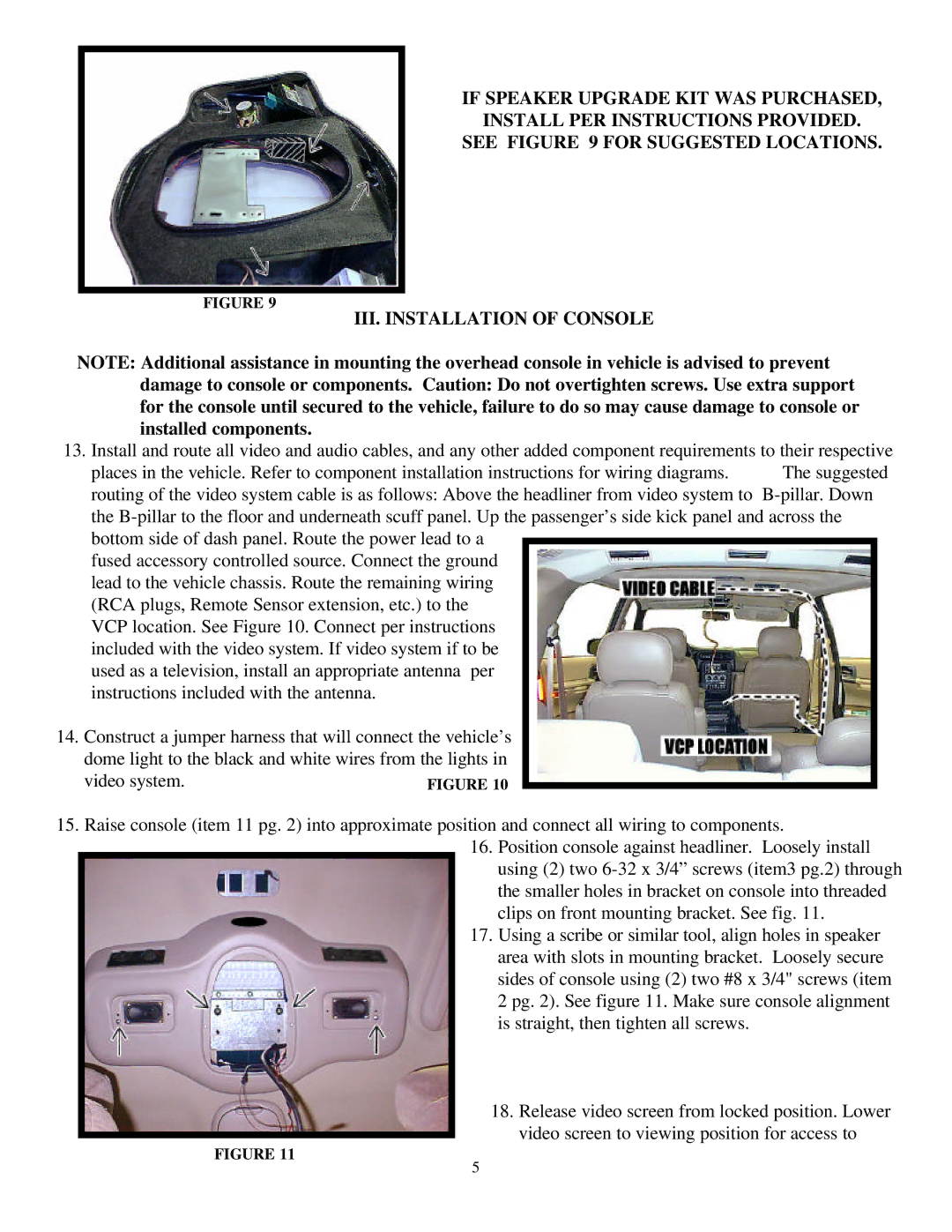
IF SPEAKER UPGRADE KIT WAS PURCHASED,
INSTALL PER INSTRUCTIONS PROVIDED.
SEE FIGURE 9 FOR SUGGESTED LOCATIONS.
FIGURE 9
III. INSTALLATION OF CONSOLE
NOTE: Additional assistance in mounting the overhead console in vehicle is advised to prevent damage to console or components. Caution: Do not overtighten screws. Use extra support for the console until secured to the vehicle, failure to do so may cause damage to console or installed components.
13. Install and route all video and audio cables, and any other added component requirements to their respective
places in the vehicle. Refer to component installation instructions for wiring diagrams. The suggested routing of the video system cable is as follows: Above the headliner from video system to
fused accessory controlled source. Connect the ground lead to the vehicle chassis. Route the remaining wiring (RCA plugs, Remote Sensor extension, etc.) to the VCP location. See Figure 10. Connect per instructions included with the video system. If video system if to be used as a television, install an appropriate antenna per instructions included with the antenna.
14.Construct a jumper harness that will connect the vehicle’s dome light to the black and white wires from the lights in
video system.
15.Raise console (item 11 pg. 2) into approximate position and connect all wiring to components.
16.Position console against headliner. Loosely install using (2) two
17.Using a scribe or similar tool, align holes in speaker area with slots in mounting bracket. Loosely secure sides of console using (2) two #8 x 3/4" screws (item 2 pg. 2). See figure 11. Make sure console alignment is straight, then tighten all screws.
18.Release video screen from locked position. Lower
video screen to viewing position for access to
FIGURE 11
5