Page 8 | YP3040 Installation Guide |
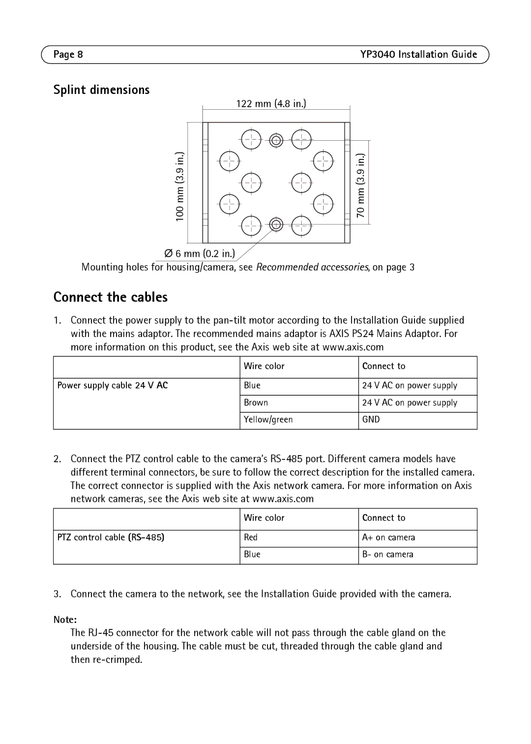
Splint dimensions
100 mm (3.9 in.)
122 mm (4.8 in.)
![]()
![]() 70 mm (3.9 in.)
70 mm (3.9 in.)
Ø6 mm (0.2 in.)
Mounting holes for housing/camera, see Recommended accessories, on page 3
Connect the cables
1. Connect the power supply to the
| Wire color | Connect to |
|
|
|
Power supply cable 24 V AC | Blue | 24 V AC on power supply |
|
|
|
| Brown | 24 V AC on power supply |
|
|
|
| Yellow/green | GND |
|
|
|
2. | Connect the PTZ control cable to the camera’s | ||
| different terminal connectors, be sure to follow the correct description for the installed camera. | ||
| The correct connector is supplied with the Axis network camera. For more information on Axis | ||
| network cameras, see the Axis web site at www.axis.com |
| |
|
|
|
|
|
| Wire color | Connect to |
|
|
| |
PTZ control cable | Red | A+ on camera | |
|
|
|
|
|
| Blue | B- on camera |
|
|
|
|
3. | Connect the camera to the network, see the Installation Guide provided with the camera. | ||
Note: |
|
| |
The