Parallel to Serial and Serial to Parallel Converter, 232SPS2 specifications
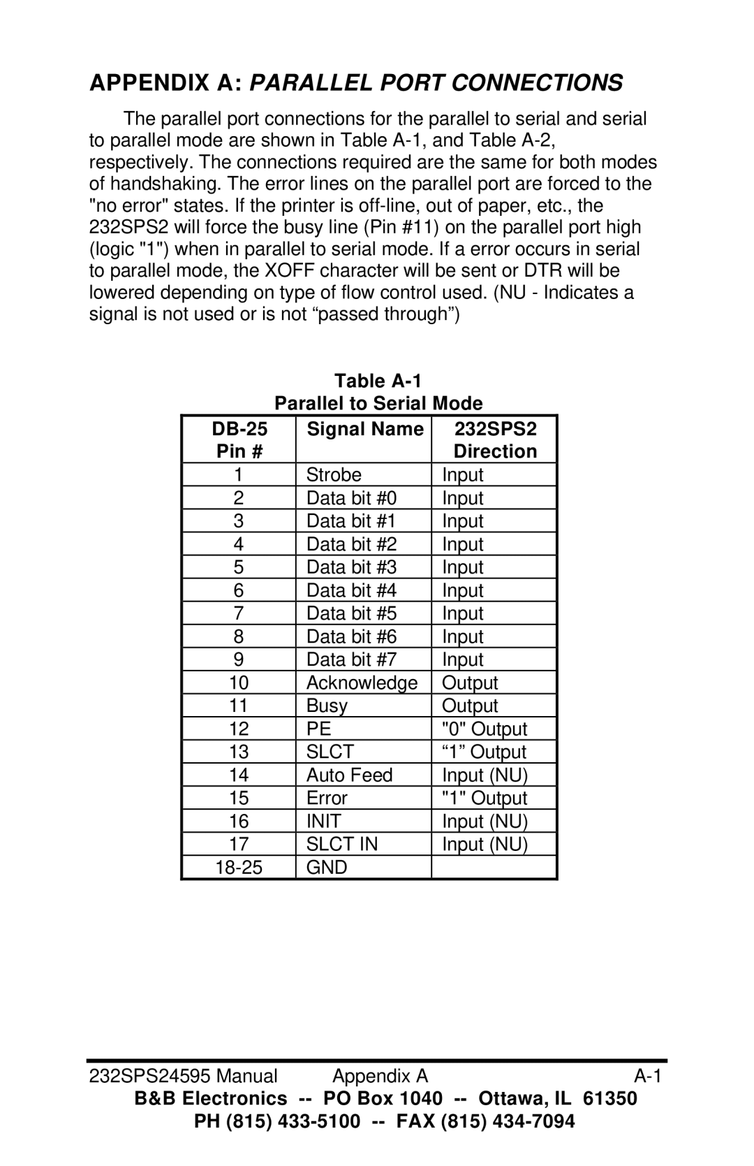
B&B Electronics 232SPS2 is a versatile, high-performance converter that serves as both a parallel to serial and serial to parallel converter. This dual functionality makes it an essential tool for various communication applications where data transfer between different formats is required. With its compact design and integrated technologies, the 232SPS2 streamlines data communication processes across various systems.One of the main features of the 232SPS2 is its ability to convert data formats seamlessly. It enables users to bridge the gap between parallel data interfaces found in older hardware and the serial interfaces commonly used in modern devices. This adaptability makes it an ideal choice for industries that rely on legacy systems and need to integrate with new technology without extensive system overhauls.
The 232SPS2 boasts several advanced technologies that enhance its performance and reliability. The device features a robust data rate up to 115.2 kbps, ensuring that it can handle high-speed data transfer requirements. This capability is further complemented by a comprehensive error checking mechanism, which helps in maintaining data integrity during transmission. The compact, rugged design also ensures that it is suitable for industrial environments where durability is crucial.
Another key characteristic of the 232SPS2 is its ease of use. It is designed with user-friendly configurations, allowing for quick setup and operation. The device is equipped with clear indicator LEDs that provide real-time feedback on status and data flow, making diagnostics straightforward for users.
The 232SPS2 supports a wide range of applications, from automation systems to data acquisition, and can interface with multiple devices. Its support for both standard and extended transmission distances provides additional flexibility, making it useful in diverse operational scenarios.
In conclusion, the B&B Electronics 232SPS2 parallel to serial and serial to parallel converter is a highly effective solution for anyone needing to integrate serial and parallel communication systems. With its excellent data transfer speeds, reliability, and user-friendly design, the 232SPS2 stands out as a leading choice for professionals seeking efficient data conversion and communication in their projects. Whether in industrial automation, telecommunications, or data acquisition, this converter demonstrates a perfect blend of technology and practicality.
