RS-422 Pinouts
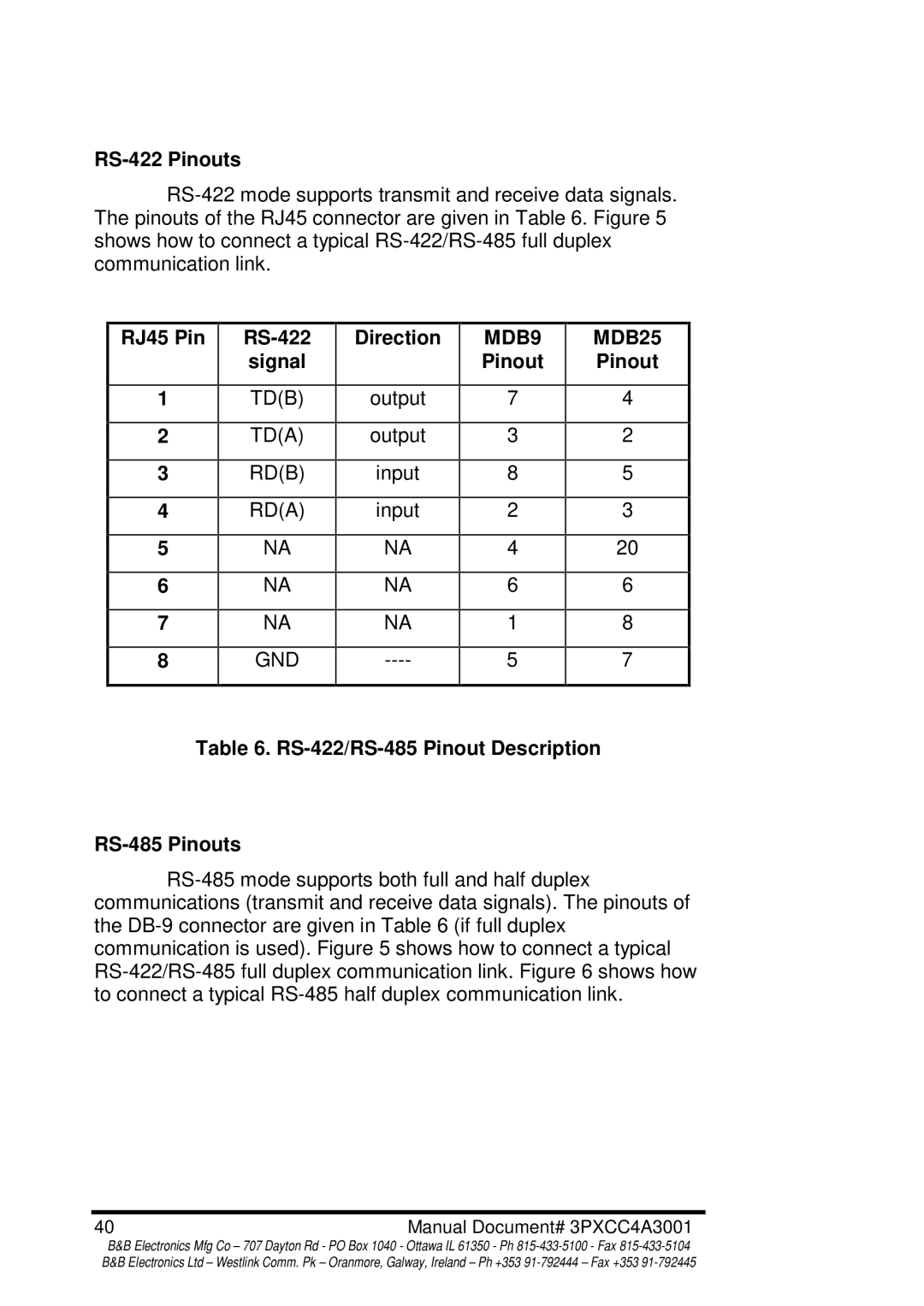
RS-422 mode supports transmit and receive data signals. The pinouts of the RJ45 connector are given in Table 6. Figure 5 shows how to connect a typical RS-422/RS-485 full duplex communication link.
RS-422
signal
TD(B)
TD(A)
RD(B)
RD(A)
NA
NA
NA
GND
Direction
output
output
input
input
NA
NA
NA
----
Table 6. RS-422/RS-485 Pinout Description
RS-485 Pinouts
RS-485 mode supports both full and half duplex communications (transmit and receive data signals). The pinouts of the DB-9 connector are given in Table 6 (if full duplex communication is used). Figure 5 shows how to connect a typical RS-422/RS-485 full duplex communication link. Figure 6 shows how to connect a typical RS-485 half duplex communication link.
40 | Manual Document# 3PXCC4A3001 |
B&B Electronics Mfg Co – 707 Dayton Rd - PO Box 1040 - Ottawa IL 61350 - Ph 815-433-5100 - Fax 815-433-5104 B&B Electronics Ltd – Westlink Comm. Pk – Oranmore, Galway, Ireland – Ph +353 91-792444 – Fax +353 91-792445

