Chapter 3 - Commands
There are only two commands required to control the 485SDD16: set output lines, and read I/O lines. Five additional commands are used for configuring the module: set module address, set turn- around delay, define I/O lines, set
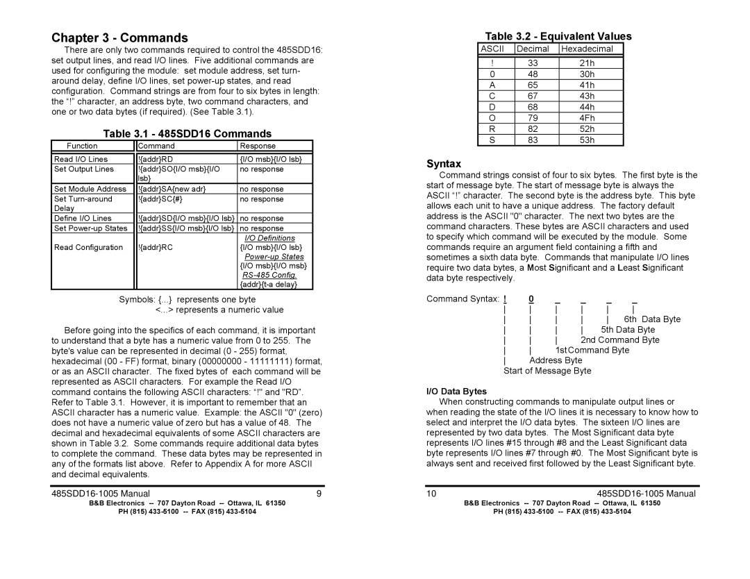
Table 3.1 - 485SDD16 Commands
Function |
| Command | Response |
|
|
|
|
Read I/O Lines |
| !{addr}RD | {I/O msb}{I/O lsb} |
Set Output Lines |
| !{addr}SO{I/O msb}{I/O | no response |
|
| lsb} |
|
Set Module Address |
| !{addr}SA{new adr} | no response |
Set |
| !{addr}SC{#} | no response |
Delay |
|
|
|
Define I/O Lines |
| !{addr}SD{I/O msb}{I/O lsb} | no response |
Set |
| !{addr}SS{I/O msb}{I/O lsb} | no response |
|
|
| I/O Definitions |
Read Configuration |
| !{addr}RC | {I/O msb}{I/O lsb} |
|
|
| |
|
|
| {I/O msb}{I/O msb} |
|
|
| |
|
|
| |
Symbols: {...} represents one byte | |||
|
| <...> represents a numeric value | |
Before going into the specifics of each command, it is important to understand that a byte has a numeric value from 0 to 255. The byte's value can be represented in decimal (0 - 255) format, hexadecimal (00 - FF) format, binary (00000000 - 11111111) format, or as an ASCII character. The fixed bytes of each command will be represented as ASCII characters. For example the Read I/O command contains the following ASCII characters: “!" and "RD”. Refer to Table 3.1. However, it is important to remember that an ASCII character has a numeric value. Example: the ASCII "0" (zero) does not have a numeric value of zero but has a value of 48. The decimal and hexadecimal equivalents of some ASCII characters are shown in Table 3.2. Some commands require additional data bytes to complete the command. These data bytes may be represented in any of the formats list above. Refer to Appendix A for more ASCII and decimal equivalents.
| 9 |
B&B Electronics | 707 Dayton Road |
PH (815) | |
Table 3.2 - Equivalent Values
ASCII | Decimal | Hexadecimal |
|
|
|
! | 33 | 21h |
0 | 48 | 30h |
A | 65 | 41h |
C | 67 | 43h |
D | 68 | 44h |
O | 79 | 4Fh |
R | 82 | 52h |
S | 83 | 53h |
Syntax
Command strings consist of four to six bytes. The first byte is the start of message byte. The start of message byte is always the ASCII “!” character. The second byte is the address byte. This byte allows each unit to have a unique address. The factory default address is the ASCII "0" character. The next two bytes are the command characters. These bytes are ASCII characters and used to specify which command will be executed by the module. Some commands require an argument field containing a fifth and sometimes a sixth data byte. Commands that manipulate I/O lines require two data bytes, a Most Significant and a Least Significant data byte respectively.
Command Syntax: ! | 0 | _ | _ | _ | _ |
6th Data Byte | |||||
5th Data Byte | |||||
2nd Command Byte | |||||
1stCommand Byte | |||||
Address Byte |
|
| |||
Start of Message Byte
I/O Data Bytes
When constructing commands to manipulate output lines or when reading the state of the I/O lines it is necessary to know how to select and interpret the I/O data bytes. The sixteen I/O lines are represented by two data bytes. The Most Significant data byte represents I/O lines #15 through #8 and the Least Significant data byte represents I/O lines #7 through #0. The Most Significant byte is always sent and received first followed by the Least Significant byte.
10485SDD16-1005 Manual
B&B Electronics
PH (815)