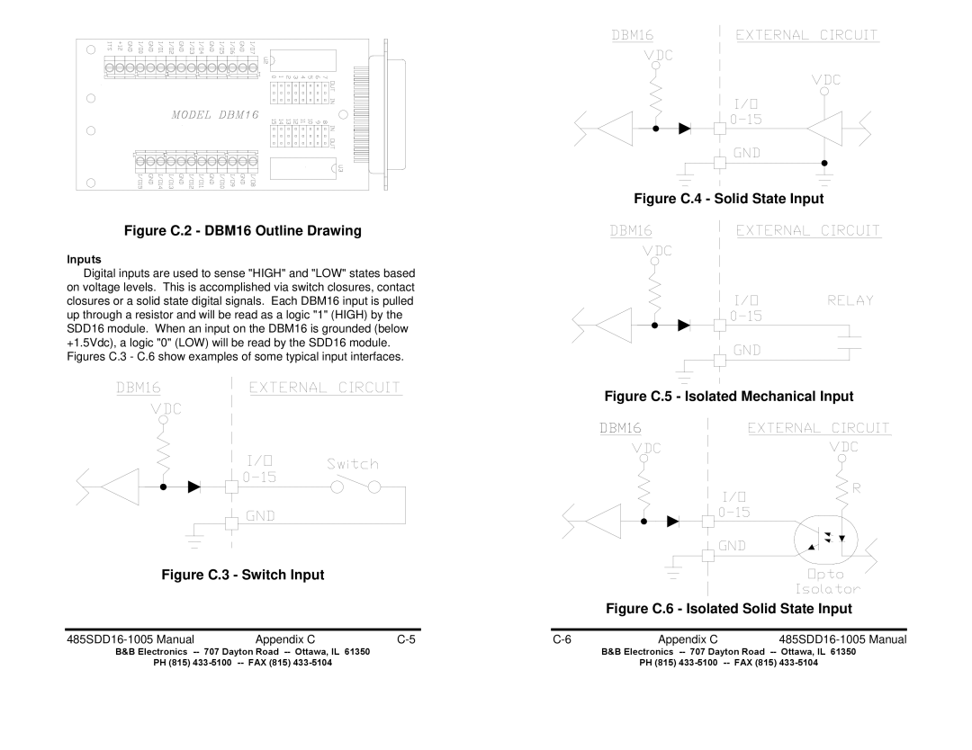
Figure C.4 - Solid State Input
Figure C.2 - DBM16 Outline Drawing
Inputs
Digital inputs are used to sense "HIGH" and "LOW" states based on voltage levels. This is accomplished via switch closures, contact closures or a solid state digital signals. Each DBM16 input is pulled up through a resistor and will be read as a logic "1" (HIGH) by the SDD16 module. When an input on the DBM16 is grounded (below +1.5Vdc), a logic "0" (LOW) will be read by the SDD16 module. Figures C.3 - C.6 show examples of some typical input interfaces.
Figure C.5 - Isolated Mechanical Input
Figure C.3 - Switch Input
Figure C.6 - Isolated Solid State Input
| Appendix C | Appendix C |
| ||
B&B Electronics |
|
| B&B Electronics | ||
PH (815) |
|
| PH (815) | ||