Chapter 6
6.2ADAM-5013 RTD Input Resistance Calibration
1.Apply power to the module and let it warm up for about 30 minutes.
2.Make sure that the module is correctly installed and is properly con- figured for the input range you want to calibrate. You can use the ADAM utility software to help in this.
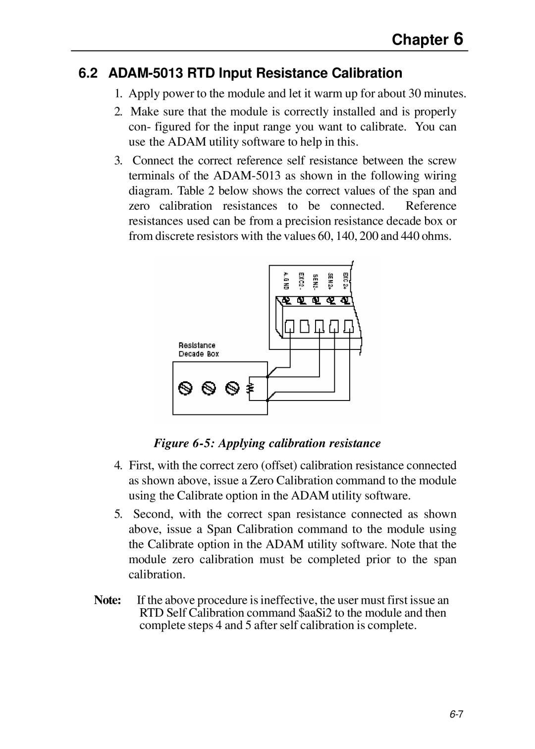
3.Connect the correct reference self resistance between the screw terminals of the
Figure 6-5: Applying calibration resistance
4.First, with the correct zero (offset) calibration resistance connected as shown above, issue a Zero Calibration command to the module using the Calibrate option in the ADAM utility software.
5.Second, with the correct span resistance connected as shown above, issue a Span Calibration command to the module using the Calibrate option in the ADAM utility software. Note that the module zero calibration must be completed prior to the span calibration.
Note: If the above procedure is ineffective, the user must first issue an RTD Self Calibration command $aaSi2 to the module and then complete steps 4 and 5 after self calibration is complete.