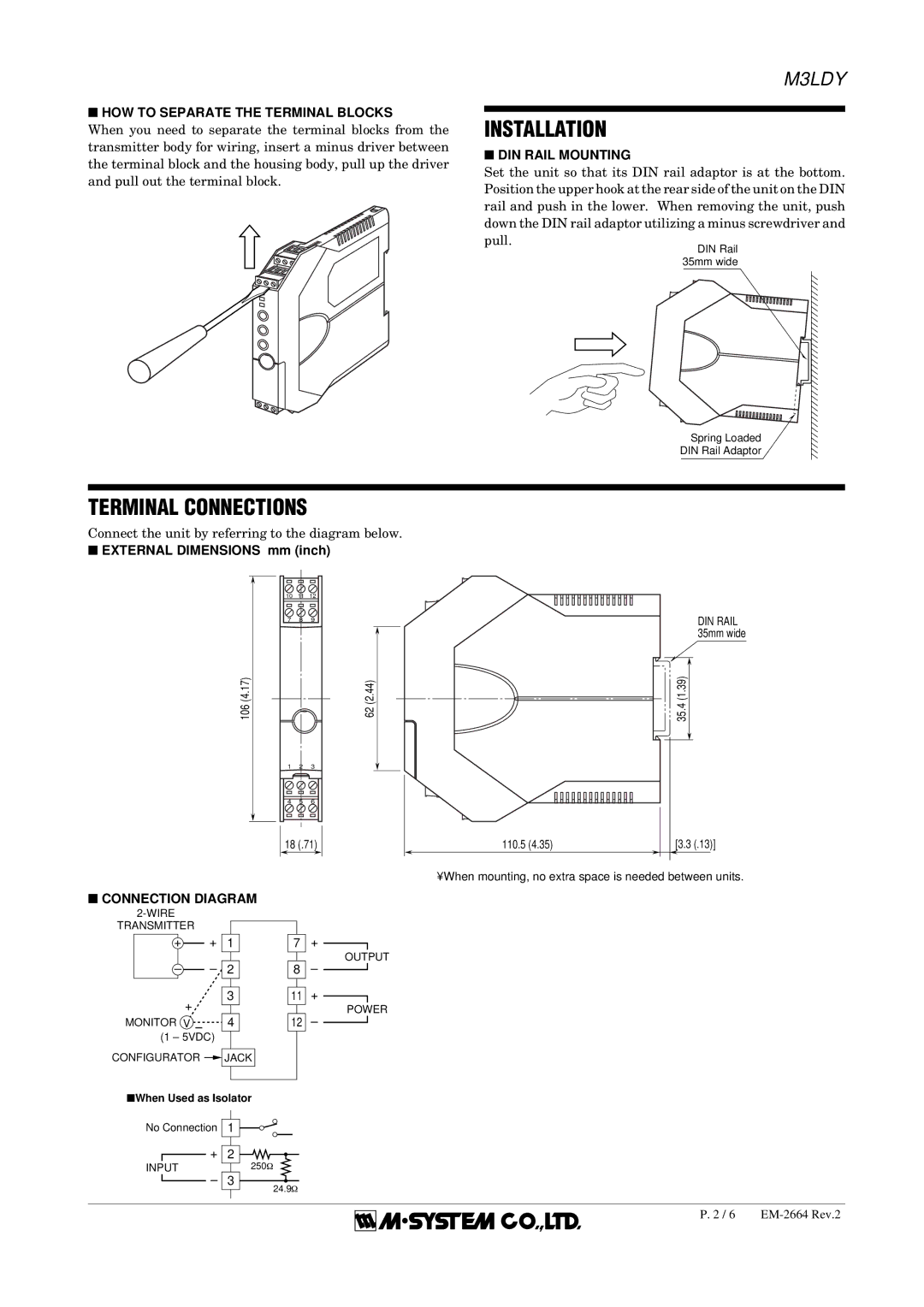
M3LDY specifications
B&B Electronics has long been recognized for its innovation in the field of industrial communications, and the M3LDY wireless modem exemplifies this commitment to quality and performance. Designed specifically for remote monitoring and telemetry applications, the M3LDY modem combines robust features with advanced technology, making it an excellent choice for those in need of reliable wireless connectivity.One of the key features of the M3LDY is its support for various communication protocols, enabling seamless integration with a range of devices. Whether it’s RS-232, RS-485, or TTL serial interfaces, the M3LDY can accommodate your specific requirements, promoting versatility in deployment. This adaptability ensures that users can easily incorporate the modem into existing systems, minimizing the need for significant redesign.
The M3LDY operates within the ISM band, which allows it to provide long-range communication capabilities while adhering to regulations for unlicensed frequencies. Its frequency-hopping spread spectrum technology enhances security and reduces the likelihood of interference, ensuring a stable connection crucial for remote data collection.
Another notable characteristic of the M3LDY is its impressive power efficiency, making it ideal for battery-operated devices. With low power consumption modes, the modem can operate for extended periods without frequent battery replacements, significantly reducing maintenance costs and downtime. This feature is particularly advantageous for energy-sensitive applications commonly found in remote monitoring scenarios.
The modem also boasts an extended temperature range, making it suitable for deployment in harsh environments. This durability ensures that the M3LDY can perform reliably in various conditions, from extreme cold to high heat, which is essential for outdoor applications.
In addition, the M3LDY is equipped with built-in diagnostics and status indicators that facilitate troubleshooting and monitoring. Users can easily assess the operational status of the modem, which aids in maintaining a seamless communication network.
With its combination of versatile communication protocols, robust security features, low power consumption, and environmental durability, B&B Electronics’ M3LDY modem is a premier choice for businesses looking to enhance their remote monitoring capabilities. By integrating advanced technology and user-friendly characteristics, the M3LDY stands out as a reliable solution in the ever-evolving landscape of industrial connectivity.

