TRANSFORMER OUTLET
3V TRANSFORMER
LOW VOLTAGE | FLAME SPARKER / |
SEE NOTE 1 | SENSOR |
IGNITION |
|
MODULE |
|
(3V) |
|
JUNCTION BOX
TRANSFORMER 3V
SPARK TO
PILOT IGNITOR
IGNITOR
MODULE
3V
IORANGE (IGNITOR)
WHITE (SENSOR)
S |
|
BLACK | PILOT ASSEMBLY |
AND VALVE ASSEMBLY | |
| MUST BE GROUNDED |
GROUND TO | (COMMON GROUND |
| WITH FIREPLACE |
FIREPLACE CHASSIS)
CHASSIS
|
| OPTIONAL | |
|
| BATTERY | |
|
| ||
ON/OFF |
|
| |
WALL SWITCH |
| ||
VALVE |
| LOW VOLTAGE | |
|
| SEE NOTE 1 | |
NEUTRAL | GROUND | REMOTE | |
CONTROL HOT | |||
|
| ||
| BLACK |
|
| OPTIONAL |
|
| BATTERY | ORANGE |
| ||
|
| |
ON/OFF | RED |
|
SWITCH | BROWN |
|
|
| |
| BROWN |
|
GREEN
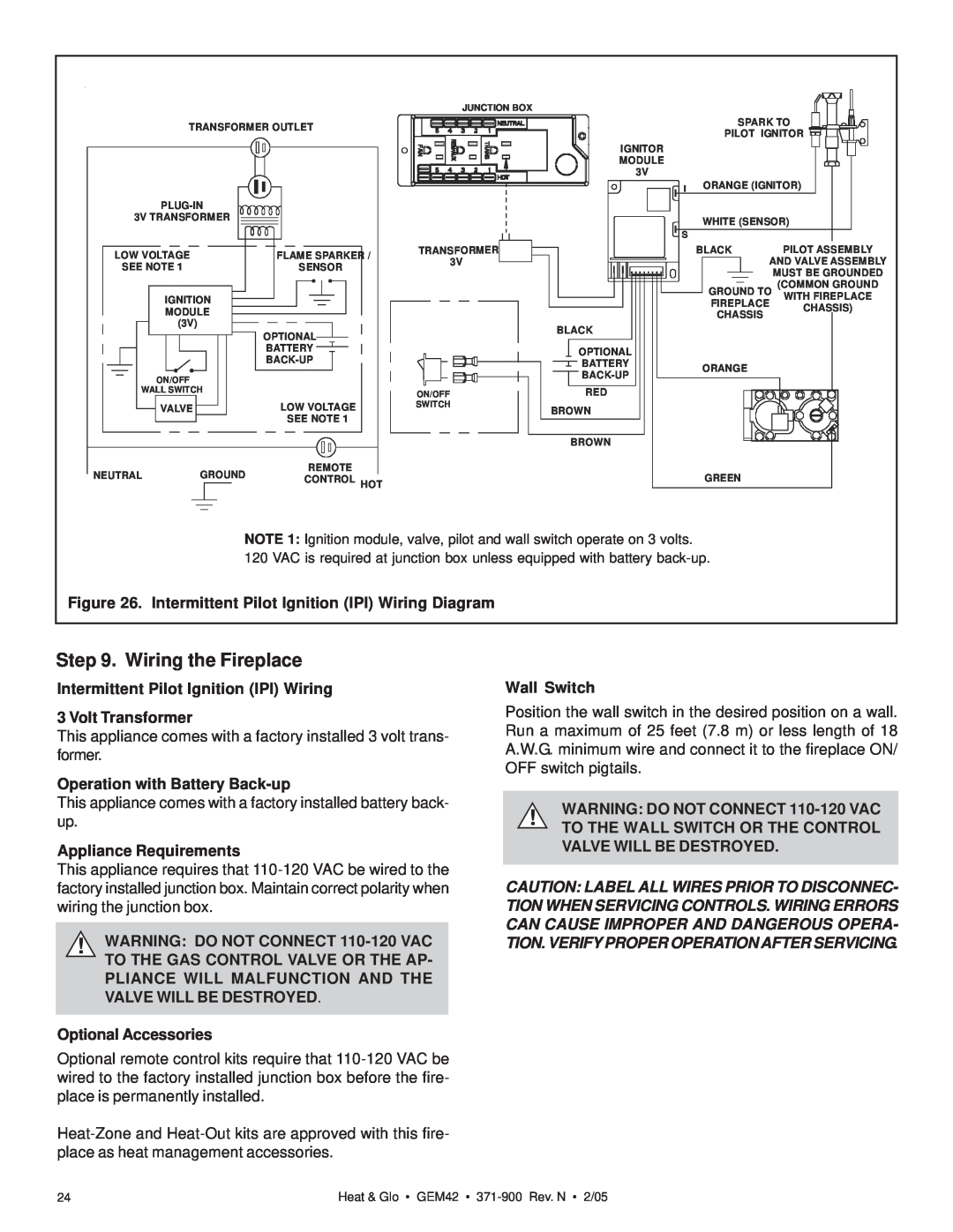
NOTE 1: Ignition module, valve, pilot and wall switch operate on 3 volts. 120 VAC is required at junction box unless equipped with battery
Figure 26. Intermittent Pilot Ignition (IPI) Wiring Diagram
Step 9. Wiring the Fireplace
Intermittent Pilot Ignition (IPI) Wiring
3 Volt Transformer
This appliance comes with a factory installed 3 volt trans- former.
Operation with Battery Back-up
This appliance comes with a factory installed battery back- up.
Appliance Requirements
This appliance requires that
!WARNING: DO NOT CONNECT
Optional Accessories
Optional remote control kits require that
Wall Switch
Position the wall switch in the desired position on a wall. Run a maximum of 25 feet (7.8 m) or less length of 18 A.W.G. minimum wire and connect it to the fireplace ON/ OFF switch pigtails.
!WARNING: DO NOT CONNECT
CAUTION: LABEL ALL WIRES PRIOR TO DISCONNEC- TION WHEN SERVICING CONTROLS. WIRING ERRORS CAN CAUSE IMPROPER AND DANGEROUS OPERA- TION. VERIFY PROPER OPERATION AFTER SERVICING.
24 | Heat & Glo • GEM42 • |