Manuals
/
Heat & Glo LifeStyle
/
Household Appliance
/
Gas Heater
Heat & Glo LifeStyle
manual
Diagram of the GEM42, Heat & Glo GEM42 371-900 Rev. N 2/05
Models:
GEM42
1
9
29
29
Download
29 pages
23.03 Kb
6
7
8
9
10
11
12
13
Install
NG, LP Exploded Parts Diagram
Wiring the Fireplace
Dimension
Maintenance
Accessories / Accessoires
Valve Assembly
Pilot Shield Adjustment
Air Shutter Setting
Safety
Page 9
Image 9
Page 8
Page 10
Page 9
Image 9
Page 8
Page 10
Contents
Installers Guide
Model
GEM42
Underwriters Laboratories Listed
This gas fireplace and vent assembly MUST be
SAFETY AND WARNING INFORMATION
READ and UNDERSTAND all instructions carefully
DO NOT USE this appliance if any part has been
Safety and Warning Information
TABLE OF CONTENTS
Service Parts Lists
Section 3 Installing the Fireplace
GEM42
Service Parts
5 Log set assembly
NG, LP Exploded Parts Diagram
Service Parts List / Liste des pièces de rechange
GEM42
ACCESSORIES / ACCESSOIRES
Intermittent Pilot Ignition
Valve Assembly
High Altitude Installations
Installation Codes
1Approvals and Codes
Appliance Certification
2Getting Started
Pre-install Preparation
Introducing the Heat & Glo Gas Fireplaces
ANY SUCH ACTION MAY POSSIBLY CAUSE A FIRE HAZARD
Heat & Glo GEM42 371-900 Rev. N 2/05
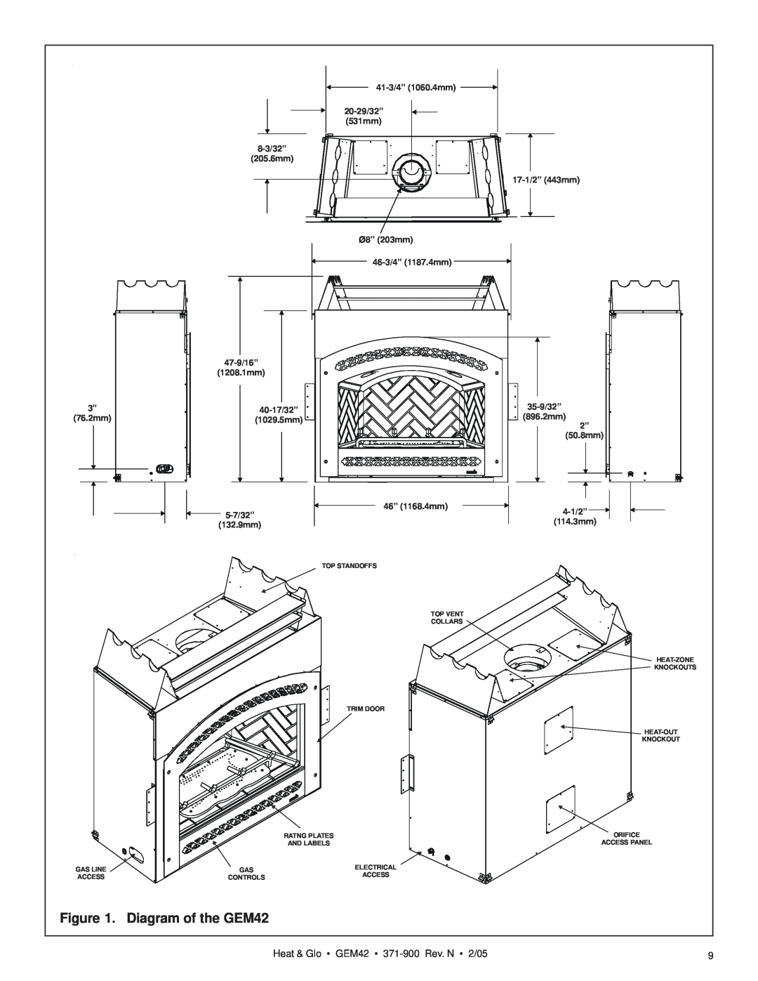
Figure 1. Diagram of the GEM42
Constructing the Fireplace Chase
3Installing the Fireplace
Step 1. Locating the Fireplace
Fireplace Dimensions, Locations
Figure 3. Framing Dimensions
Step 2. Framing the Fireplace
47-1/2”
47-3/4”
DVP90ST
NOTE PIPES OVERLAP 1-1/4 INCHES AT EACH JOINT
A. Vent System Approvals
Step 3. Installing the Vent System
TEMS OR COMPONENTS MAY BE USED
Identifying Vent Components
STRAIGHT UP
Pilot Shield Adjustment
Flue Restrictor Instructions
VERTICAL VENTING V FT 40 MAX. 12.4 M
TWO 2 90 o
VENTING WITH
ELBOWS
VENTING WITH ONE 1 90 ELBOW
H FT
V FT
VENTING WITH THREE 3 90 ELBOWS
H + H 1 FT
3. Install Support Brackets
B. Installing Vent Components
Venting Out the Top Vent
1. Attach the First Vent Component to the Starting Collars
Cut a 10-inch by 12-inch 254mm X 305mm hole through the wall
4. Install Firestops
Figure 15. 10 x 12 Hole and Vent Pipe
Figure 16. Heat Shield, Interior & Exterior Firestops
Attic Firestop
C. Vent Termination
WARNING THE TERMINATION CAP MUST BE
POSITIONED SO THAT THE ARROW IS POINT- ING UP
electrical service
= AREA WHERE TERMINAL IS NOT PERMITTED
not to be installed above a gas
meter/regulator assembly within
WARNING MAJOR U.S. BUILDING CODES SPECIFY MINIMUM CHIMNEY AND/OR
Step 4. Positioning, Leveling and Securing the Fireplace
Figure 22. Minimum Height from Roof to Lowest Discharge Opening
Figure 23. Proper Positioning
Heat-Out Kit
Step 5. Installing the Optional Heat-Out or Heat-Zone Kits
Heat-Zone Kit
Step 6 The Gas Control System
Step 8. Gas Pressure Requirements
Step 7. The Gas Supply Line
Pressure
Natural Gas
Figure 26. Intermittent Pilot Ignition IPI Wiring Diagram
Step 9. Wiring the Fireplace
Intermittent Pilot Ignition IPI Wiring 3 Volt Transformer
Operation with Battery Back-up
Figure 27. Fan Wiring Diagram
Step 10. Finishing
WARNING WHEN FINISHING THE FIREPLACE
FINISH WALL MATERIAL
Facing Requirements
IMPORTANT INSTALLATION NOTE
Figure 31. Facing Template Dimensions
Facing Thickness from 3/4” to 1-1/4”
Installing the Trim
Step 11. Installing Trim, Logs and Ember Material
Figure 34. Glass Assembly
Glass Specifications GEM42 CERAMIC
Step 12. Before Lighting the Fireplace
After the Installation
Step 13. Lighting the Fireplace
Double-check for faulty components
4Maintaining and Servicing Your Fireplace
Fireplace Maintenance
Cleaning Flame Sensor Rod IPI Systems Frequency Annually
Cleaning Glass Door
Top
Page
Image
Contents