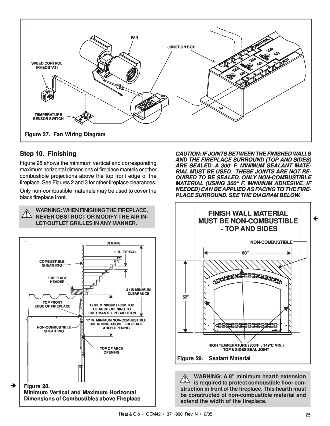
FAN |
JUNCTION BOX |
SPEED CONTROL |
(RHEOSTAT) |
TEMPERATURE |
SENSOR SWITCH |
Figure 27. Fan Wiring Diagram |
Step 10. Finishing
Figure 28 shows the minimum vertical and corresponding maximum horizontal dimensions of fireplace mantels or other combustible projections above the top front edge of the fireplace. See Figures 2 and 3 for other fireplace clearances.
Only
WARNING: WHEN FINISHING THE FIREPLACE,
!NEVER OBSTRUCT OR MODIFY THE AIR IN- LET/OUTLET GRILLES IN ANY MANNER.
| CEILING |
| 1 IN. TYPICAL |
COMBUSTIBLE | 12” |
11” | |
SHEATHING | 10” |
| 9” |
| 8” |
| 7” |
FIREPLACE | 6” |
HEADER | 5” |
| 4” |
| 3” |
2” | 31 IN MINIMUM |
1” | CLEARANCE |
TOP FRONT | 17 IN. MINIMUM FROM TOP |
EDGE OF FIREPLACE | |
| OF ARCH OPENING TO |
FIRST MANTEL PROJECTION | |
17 IN. MINIMUM | |
SHEATHING ABOVE FIREPLACE | |
ARCH OPENING | |
SHEATHING |
|
| TOP OF ARCH |
| OPENING |
ÎFigure 28.
Minimum Vertical and Maximum Horizontal Dimensions of Combustibles above Fireplace
CAUTION: IF JOINTS BETWEEN THE FINISHED WALLS AND THE FIREPLACE SURROUND (TOP AND SIDES) ARE SEALED, A 300° F. MINIMUM SEALANT MATE-
RIAL MUST BE USED. THESE JOINTS ARE NOT RE- QUIRED TO BE SEALED. ONLY
| FINISH WALL MATERIAL | Í | |
MUST BE | |||
| |||
| - TOP AND SIDES |
| |
|
|
| |
| 60” |
| |
52” |
|
| |
| HIGH TEMPERATURE (3000F / 1490C MIN.) |
| |
| TOP & SIDES SEAL JOINT |
| |
Figure 29. | Sealant Material |
| |
!WARNING: A 8” minimum hearth extension is required to protect combustible floor con-
struction in front of the fireplace. This hearth must be constructed of
Heat & Glo • GEM42 • | 25 |