Step 5. Installing the Optional Heat-Out or Heat-Zone Kits
Heat-Out Kit
1.Remove the
2.Center the rear collar around the exposed hole and at- tach it to the fireplace with 3 screws. NOTE: Remove the bottom knockout on the collar for typical 2 x 4 or 2 x 6 wall construction. See Figure 24.
3.Cut and frame a 12” wide x 10” tall (305 x 254mm) hole in the exterior wall. The center of the hole will be
4.Install the interior firestop with the hole towards the top. Secure the firestop to wall framing members.
Reference the
NOTE: There must be NO INSULATION or other com- bustibles inside the framed firestop opening.
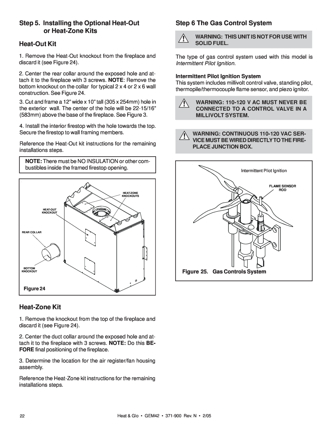
KNOCKOUTS |
KNOCKOUT |
REAR COLLAR |
BOTTOM |
KNOCKOUT |
Figure 24 |
Heat-Zone Kit
1.Remove the knockout from the top of the fireplace and discard it (see Figure 24).
2.Center the duct collar around the exposed hole and at- tach it to the fireplace with 3 screws. NOTE: Do this BE- FORE final positioning of the fireplace.
3.Determine the location for the air register/fan housing assembly.
Reference the
Step 6 The Gas Control System
!WARNING: THIS UNIT IS NOT FOR USE WITH SOLID FUEL.
The type of gas control system used with this model is Intermittent Pilot Ignition.
Intermittent Pilot Ignition System
This system includes millivolt control valve, standing pilot, thermopile/thermocouple flame sensor, and piezo ignitor.
!WARNING:
!WARNING: CONTINUOUS 110-120 VAC SER-
VICE MUST BE WIRED DIRECTLY TO THE FIRE- PLACE JUNCTION BOX.
Intermittent Pilot Ignition
FLAME SENSOR
ROD
Figure 25. Gas Controls System
22 | Heat & Glo • GEM42 • |