The
Name | Description | Direction | DB25M |
|
|
| Pin |
|
|
|
|
Shield | Shield | 1 | |
TD (A) − | Transmit Data A | Output | 2 |
RD (A) − | Receive Data A | Input | 3 |
GND | Signal Ground | 7 | |
TD (B) + | Transmit Data B | Output | 14 |
RD (B) + | Receive Data B | Input | 16 |
Table 2: RS-422/485 Pinouts
With
Note that the EIA
RS-485 Mode
To configure the port for
1.Set four jumpers of JP2
2.Set the top jumper "TX" of JP4 to the “485” (right) position.
3.For
4.Set the JP1 Control jumper to select the type of
Documentation Number | Chapter 2 | 9 |
B&B Electronics Mfg Co – 707 Dayton Rd - PO Box 1040 - Ottawa IL 61350 - Ph
5.The bottom jumper "Termination" of JP4 switches the 120 Ω Termination resistor IN or OUT. Typically this resistor is not used. In some cases, using high baud rates and very long cables, termination is needed. See B&B’s free
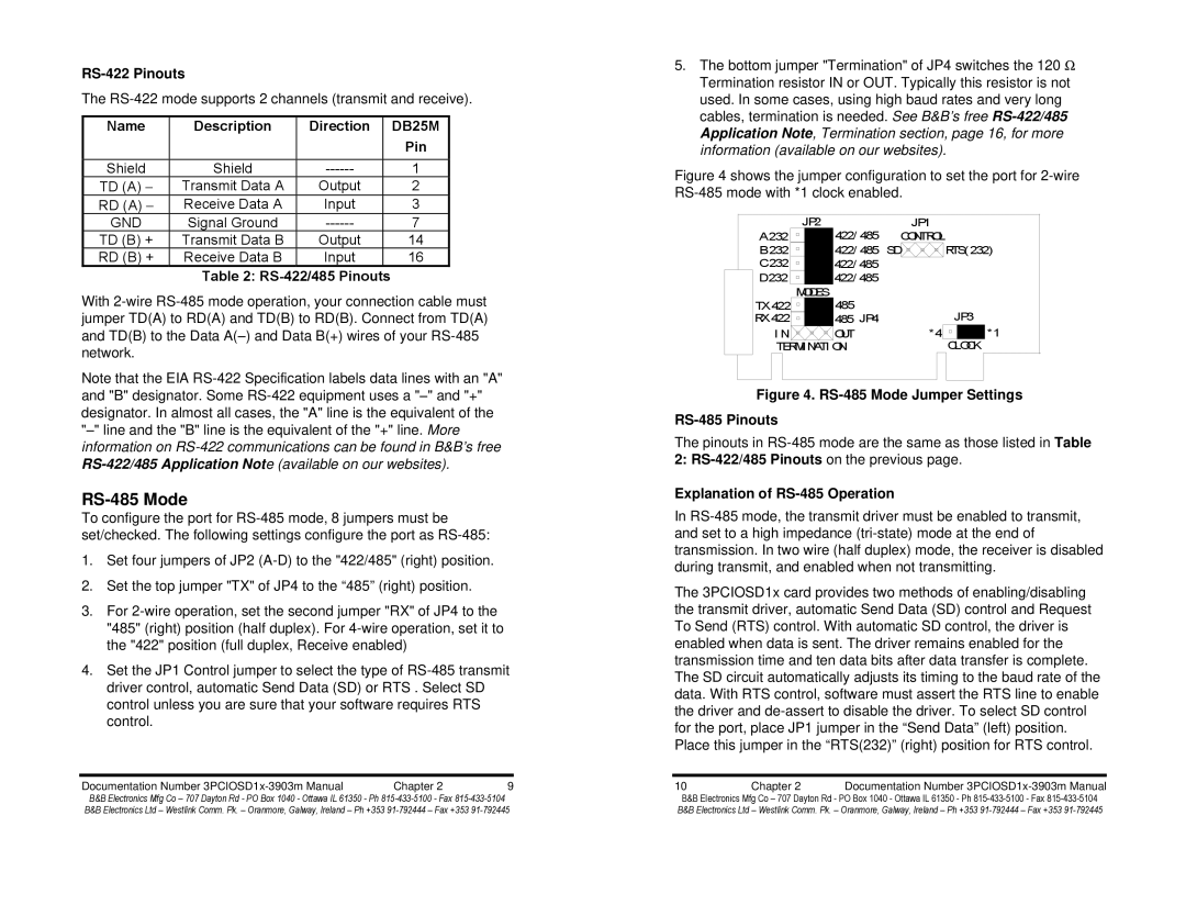
Figure 4 shows the jumper configuration to set the port for 2-wire RS-485 mode with *1 clock enabled.
| JP2 | 422/ 485 |
| JP1 | ||
A 232 |
|
| CONTROL | |||
B 232 |
|
| 422/ 485 | SD |
| RTS(232) |
C232 |
|
| 422/ 485 |
|
|
|
|
|
|
|
| ||
D232 |
|
| 422/ 485 |
|
|
|
| MODES |
|
|
TX 422 | 485 |
| JP3 |
RX 422 | 485 JP4 |
| |
I N | OUT | *4 | *1 |
TERMI NATI ON |
| CLOCK | |
Figure 4. RS-485 Mode Jumper Settings
RS-485 Pinouts
The pinouts in
2:
Explanation of RS-485 Operation
In
The 3PCIOSD1x card provides two methods of enabling/disabling the transmit driver, automatic Send Data (SD) control and Request To Send (RTS) control. With automatic SD control, the driver is enabled when data is sent. The driver remains enabled for the transmission time and ten data bits after data transfer is complete. The SD circuit automatically adjusts its timing to the baud rate of the data. With RTS control, software must assert the RTS line to enable the driver and
10 | Chapter 2 | Documentation Number |
B&B Electronics Mfg Co – 707 Dayton Rd - PO Box 1040 - Ottawa IL 61350 - Ph