Chapter 2. Setup
Hardware Setup
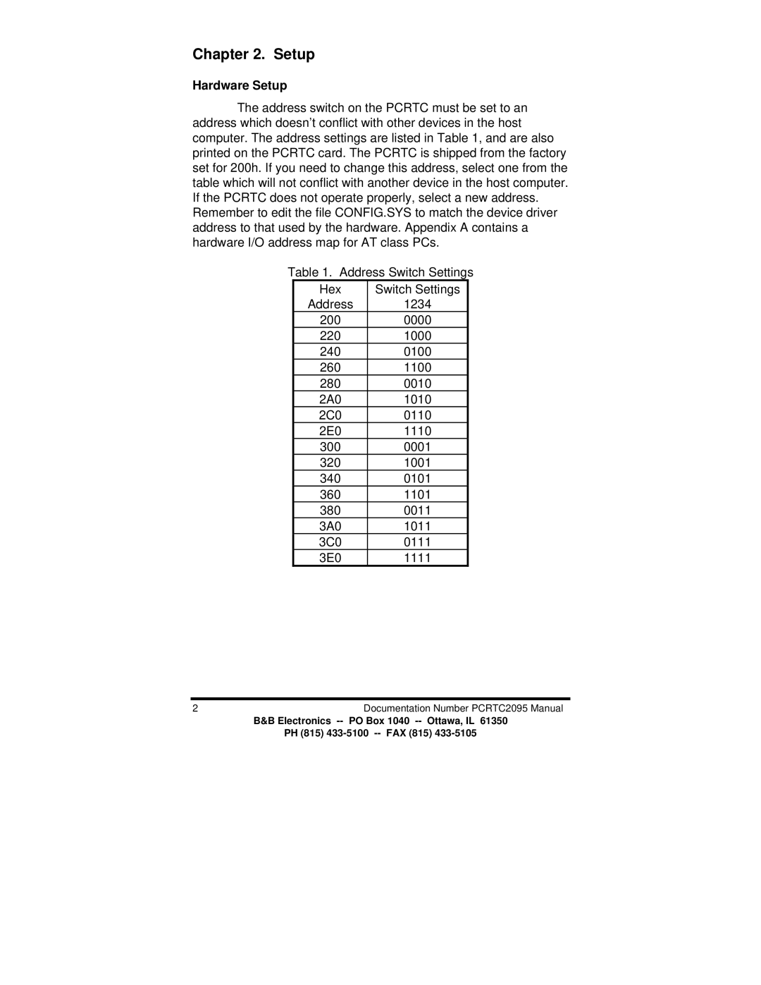
The address switch on the PCRTC must be set to an address which doesn’t conflict with other devices in the host computer. The address settings are listed in Table 1, and are also printed on the PCRTC card. The PCRTC is shipped from the factory set for 200h. If you need to change this address, select one from the table which will not conflict with another device in the host computer. If the PCRTC does not operate properly, select a new address. Remember to edit the file CONFIG.SYS to match the device driver address to that used by the hardware. Appendix A contains a hardware I/O address map for AT class PCs.
Table 1. Address Switch Settings
Hex | Switch Settings |
Address | 1234 |
200 | 0000 |
220 | 1000 |
240 | 0100 |
260 | 1100 |
280 | 0010 |
2A0 | 1010 |
2C0 | 0110 |
2E0 | 1110 |
300 | 0001 |
320 | 1001 |
340 | 0101 |
360 | 1101 |
380 | 0011 |
3A0 | 1011 |
3C0 | 0111 |
3E0 | 1111 |
2 | Documentation Number PCRTC2095 Manual |
B&B Electronics | PO Box 1040 |
PH (815)
