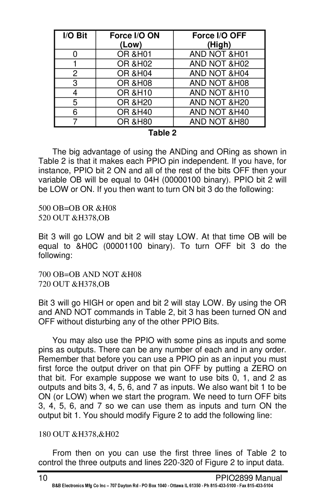
I/O Bit | Force I/O ON | Force I/O OFF |
| (Low) | (High) |
0 | OR &H01 | AND NOT &H01 |
1 | OR &H02 | AND NOT &H02 |
2 | OR &H04 | AND NOT &H04 |
3 | OR &H08 | AND NOT &H08 |
4 | OR &H10 | AND NOT &H10 |
5 | OR &H20 | AND NOT &H20 |
6 | OR &H40 | AND NOT &H40 |
7 | OR &H80 | AND NOT &H80 |
Table 2
The big advantage of using the ANDing and ORing as shown in Table 2 is that it makes each PPIO pin independent. If you have, for instance, PPIO bit 2 ON and all of the rest of the bits OFF then your variable OB will be equal to 04H (00000100 binary). PPIO bit 2 will be LOW or ON. If you then want to turn ON bit 3 do the following:
500 OB=OB OR &H08
520 OUT &H378,OB
Bit 3 will go LOW and bit 2 will stay LOW. At that time OB will be equal to &H0C (00001100 binary). To turn OFF bit 3 do the following:
700 OB=OB AND NOT &H08
720 OUT &H378,OB
Bit 3 will go HIGH or open and bit 2 will stay LOW. By using the OR and AND NOT commands in Table 2, bit 3 has been turned ON and OFF without disturbing any of the other PPIO Bits.
You may also use the PPIO with some pins as inputs and some pins as outputs. There can be any number of each and in any order. Remember that before you can use a PPIO pin as an input you must first force the output driver on that pin OFF by putting a ZERO on that bit. For example suppose we want to use bits 0, 1, and 2 as outputs and bits 3, 4, 5, 6, and 7 as inputs. We also want bit 1 to be ON (or LOW) when we start the program. We need to turn OFF bits 3, 4, 5, 6, and 7 so we can use them as inputs and turn ON the output bit 1. You should modify Figure 2 to add the following line:
180 OUT &H378,&H02
From then on you can use the first three lines of Table 2 to control the three outputs and lines
10 | PPIO2899 Manual |
B&B Electronics Mfg Co Inc – 707 Dayton Rd - PO Box 1040 - Ottawa IL 61350 - Ph