Section 4
Operation
Operator Control Panel
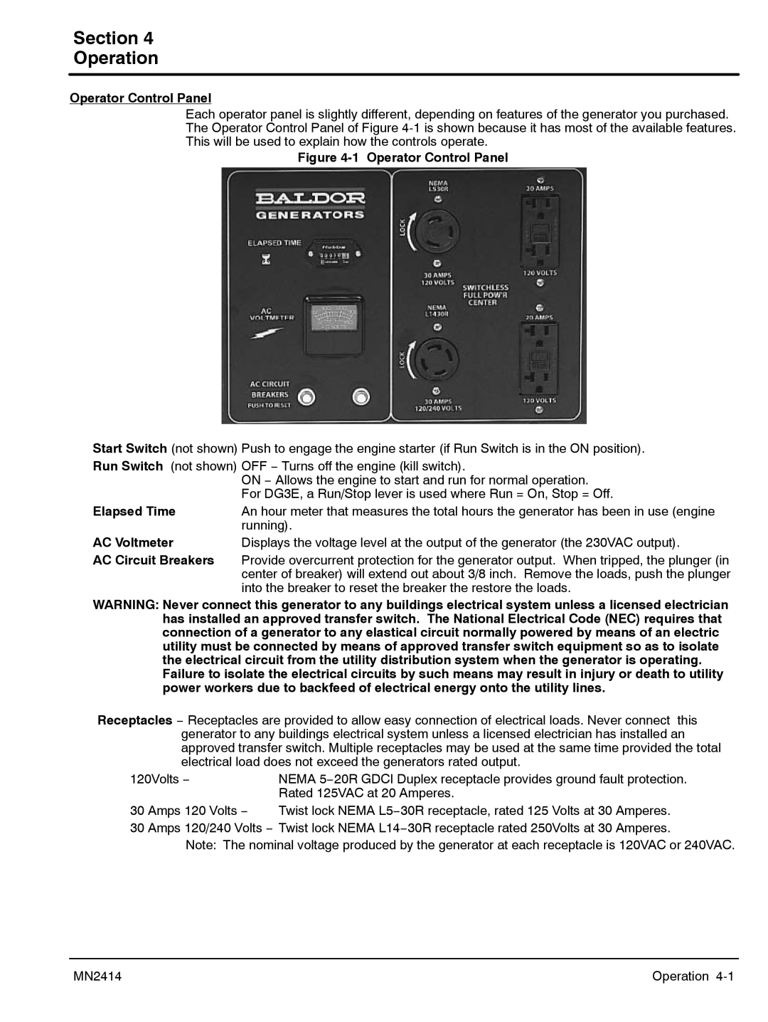
Each operator panel is slightly different, depending on features of the generator you purchased. The Operator Control Panel of Figure
Figure 4-1 Operator Control Panel
Start Switch (not shown) Push to engage the engine starter (if Run Switch is in the ON position). Run Switch (not shown) OFF − Turns off the engine (kill switch).
| ON − Allows the engine to start and run for normal operation. |
| For DG3E, a Run/Stop lever is used where Run = On, Stop = Off. |
Elapsed Time | An hour meter that measures the total hours the generator has been in use (engine |
| running). |
AC Voltmeter | Displays the voltage level at the output of the generator (the 230VAC output). |
AC Circuit Breakers | Provide overcurrent protection for the generator output. When tripped, the plunger (in |
| center of breaker) will extend out about 3/8 inch. Remove the loads, push the plunger |
| into the breaker to reset the breaker the restore the loads. |
WARNING: Never connect this generator to any buildings electrical system unless a licensed electrician has installed an approved transfer switch. The National Electrical Code (NEC) requires that connection of a generator to any elastical circuit normally powered by means of an electric utility must be connected by means of approved transfer switch equipment so as to isolate the electrical circuit from the utility distribution system when the generator is operating. Failure to isolate the electrical circuits by such means may result in injury or death to utility power workers due to backfeed of electrical energy onto the utility lines.
Receptacles − Receptacles are provided to allow easy connection of electrical loads. Never connect this generator to any buildings electrical system unless a licensed electrician has installed an approved transfer switch. Multiple receptacles may be used at the same time provided the total electrical load does not exceed the generators rated output.
120Volts − | NEMA 5−20R GDCI Duplex receptacle provides ground fault protection. | ||
|
| Rated 125VAC at 20 Amperes. |
|
30 | Amps 120 Volts − | Twist lock NEMA L5−30R receptacle, rated 125 Volts at 30 | Amperes. |
30 | Amps 120/240 Volts − Twist lock NEMA L14−30R receptacle rated 250Volts at 30 | Amperes. | |
Note: The nominal voltage produced by the generator at each receptacle is 120VAC or 240VAC.
MN2414 | Operation |