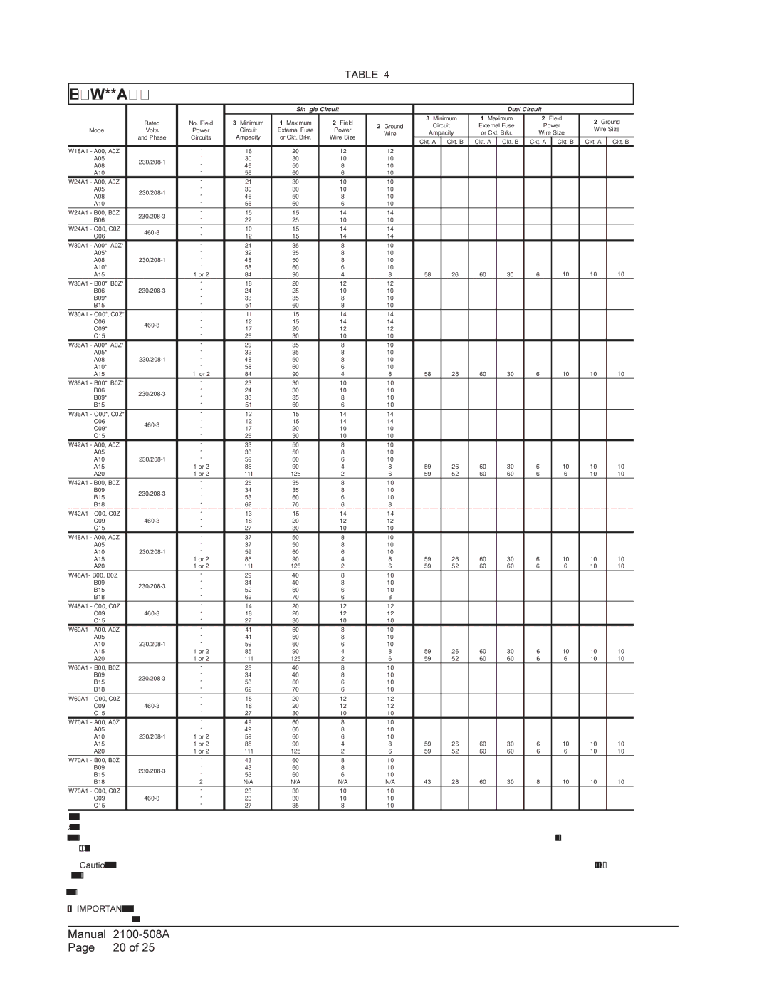
TABLE 4

Electrical Specifications — W**A Series


Single Circuit


Dual Circuit


Rated

No. Field

3 Minimum

1 Maximum

2 Field


3 Minimum

1 Maximum

2 Field

2 Ground


2 Ground

Circuit

External Fuse

Power

Model

Volts

Power

Circuit

External Fuse

Power

Wire Size

Wire

Ampacity

or Ckt. Brkr.

Wire Size


and Phase

Circuits

Ampacity

or Ckt. Brkr.

Wire Size


Ckt. A

Ckt. B

Ckt. A

Ckt. B

Ckt. A

Ckt. B

Ckt. A

Ckt. B

W18A1 - A00, A0Z


1

16

20

12

12


A05

230/208-1

1

30

30

10

10


A08

1

46

50

8

10


A10


1

56

60

6

10


W24A1 - A00, A0Z


1

21

30

10

10


A05

230/208-1

1

30

30

10

10


A08

1

46

50

8

10


A10


1

56

60

6

10


W24A1 - B00, B0Z

230/208-3

1

15

15

14

14


B06

1

22

25

10

10


W24A1 - C00, C0Z

460-3

1

10

15

14

14


C06

1

12

15

14

14


W30A1 - A00*, A0Z*


1

24

35

8

10


A05*


1

32

35

8

10


A08

230/208-1

1

48

50

8

10


A10*


1

58

60

6

10


A15


1 or 2

84

90

4

8

58

26

60

30

6

10

10

10

W30A1 - B00*, B0Z*


1

18

20

12

12


B06

230/208-3

1

24

25

10

10


B09*


1

33

35

8

10


B15


1

51

60

8

10


W30A1 - C00*, C0Z*


1

11

15

14

14


C06

460-3

1

12

15

14

14


C09*

1

17

20

12

12


C15


1

26

30

10

10


W36A1 - A00*, A0Z*


1

29

35

8

10


A05*


1

32

35

8

10


A08

230/208-1

1

48

50

8

10


A10*


1

58

60

6

10


A15


1 or 2

84

90

4

8

58

26

60

30

6

10

10

10

W36A1 - B00*, B0Z*


1

23

30

10

10


B06

230/208-3

1

24

30

10

10


B09*

1

33

35

8

10


B15


1

51

60

6

10


W36A1 - C00*, C0Z*


1

12

15

14

14


C06

460-3

1

12

15

14

14


C09*

1

17

20

10

10


C15


1

26

30

10

10


W42A1 - A00, A0Z


1

33

50

8

10


A05


1

33

50

8

10


A10

230/208-1

1

59

60

6

10


A15


1 or 2

85

90

4

8

59

26

60

30

6

10

10

10

A20


1 or 2

111

125

2

6

59

52

60

60

6

6

10

10

W42A1 - B00, B0Z


1

25

35

8

10


B09

230/208-3

1

34

35

8

10


B15

1

53

60

6

10


B18


1

62

70

6

8


W42A1 - C00, C0Z


1

13

15

14

14


C09

460-3

1

18

20

12

12


C15


1

27

30

10

10


W48A1 - A00, A0Z


1

37

50

8

10


A05


1

37

50

8

10


A10

230/208-1

1

59

60

6

10


A15


1 or 2

85

90

4

8

59

26

60

30

6

10

10

10

A20


1 or 2

111

125

2

6

59

52

60

60

6

6

10

10

W48A1- B00, B0Z


1

29

40

8

10


B09

230/208-3

1

34

40

8

10


B15

1

52

60

6

10


B18


1

62

70

6

8


W48A1 - C00, C0Z


1

14

20

12

12


C09

460-3

1

18

20

12

12


C15


1

27

30

10

10


W60A1 - A00, A0Z


1

41

60

8

10


A05


1

41

60

8

10


A10

230/208-1

1

59

60

6

10


A15


1 or 2

85

90

4

8

59

26

60

30

6

10

10

10

A20


1 or 2

111

125

2

6

59

52

60

60

6

6

10

10

W60A1 - B00, B0Z


1

28

40

8

10


B09

230/208-3

1

34

40

8

10


B15

1

53

60

6

10


B18


1

62

70

6

10


W60A1 - C00, C0Z


1

15

20

12

12


C09

460-3

1

18

20

12

12


C15


1

27

30

10

10


W70A1 - A00, A0Z


1

49

60

8

10


A05


1

49

60

8

10


A10

230/208-1

1 or 2

59

60

6

10


A15


1 or 2

85

90

4

8

59

26

60

30

6

10

10

10

A20


1 or 2

111

125

2

6

59

52

60

60

6

6

10

10

W70A1 - B00, B0Z


1

43

60

8

10


B09

230/208-3

1

43

60

8

10


B15

1

53

60

6

10


B18


2

N/A

N/A

N/A

N/A

43

28

60

30

8

10

10

10

W70A1 - C00, C0Z


1

23

30

10

10


C09

460-3

1

23

30

10

10


C15


1

27

35

8

10


1Maximum size of the time delay fuse or HACR type circuit breaker for protection of field wiring conductors.

2 Based on 75C copper wire. All wiring must conform to the National Electrical Code and all local codes.

3 These “Minimum Circuit Ampacity” values are to be used for sizing the field power conductors. Refer to the National Electrical code (latest version), Article 310 for power conductor sizing.

Caution: When more than one field power circuit is run through one conduit, the conductors must be derated. Pay special attention to note 8 of Table 310 regarding Ampacity Adjustment Factors when more than three (3) current carrying conductors are in a raceway.

* Top outlet supply option is available only factory installed and only on the selected models.

IMPORTANT: While this electrical data is presented as a guide, it is important to electrically connect properly sized fuses and conductor wires in accordance with the National Electrical Code and all local codes.

Manual

2100-508A

Page

20 of 25

Page 20
Image 20
Bard 1 W48A1, W42L, W70L1, W70A1 installation instructions Electrical Specifications W**A Series

W70A1, W70L1, W42L, 1 W48A1 specifications

The Bard range of products, specifically the W24L1, W48L1, W42L1, W70A1, and W60A1 models, showcases advanced engineering aimed at providing efficient heating and cooling solutions. Each model comes with distinctive features and technologies tailored to meet various residential and commercial needs.

Starting with the W24L1 model, it is designed for compact spaces while delivering powerful performance. Its heating capacity is optimal for smaller areas, making it suitable for residential applications. The W24L1 incorporates advanced inverter technology, ensuring energy efficiency and reducing operational costs. This model is equipped with a user-friendly interface, enabling easy control and monitoring of settings.

Next is the W48L1, which offers increased capacity for larger spaces. This model is characterized by its robust build and enhanced airflow system that ensures uniform heating and cooling throughout the environment. The W48L1 utilizes environmentally friendly refrigerants, highlighting Bard’s commitment to sustainability. Its smart technology integration allows for seamless compatibility with smart home systems, providing added convenience for users.

The W42L1 model stands out for its versatility in both heating and cooling applications. It is engineered with high-efficiency components, which contribute to lower energy consumption. Features like programmable thermostats and variable speed fans enhance user comfort and adjust to varying demand. The W42L1 also comes with a durable construction, ensuring longevity and reliability even in challenging conditions.

For those demanding even higher performance, the W70A1 model caters to significant heating and cooling requirements. This unit is designed to tackle extreme weather conditions and is often favored for industrial applications. The W70A1 employs advanced heat exchanger technology, improving efficiency and reducing energy loss. Moreover, its rugged design enables operation in harsh environments without compromising performance.

Lastly, the W60A1 represents a harmonious blend of efficiency and power. It is particularly well-suited for mid-sized applications, combining the best features from the other models. The W60A1 integrates sophisticated microprocessor controls that optimize performance while ensuring compatibility with emerging smart technology platforms. Its energy-efficient design means lower operating costs while delivering impressive comfort levels.

In summary, Bard's W24L1, W48L1, W42L1, W70A1, and W60A1 models are engineered to deliver superior heating and cooling solutions across a variety of environments. With a focus on energy efficiency, advanced technologies, and user-friendly interfaces, these models exemplify Bard's commitment to innovation and sustainability in climate control systems.