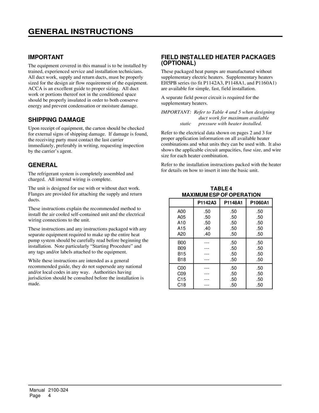
P1060A1, P1142A3, P1148A1 specifications
Bard P1148A1, P1142A3, and P1060A1 are high-performance vascular access products designed to meet the diverse needs of medical professionals in various healthcare settings. These devices, developed by Bard, are renowned for their innovative technologies and superior characteristics that enhance patient care and facilitate clinical procedures.The Bard P1148A1 is a peripherally inserted central catheter (PICC) designed for long-term intravenous therapy, including chemotherapy and antibiotics. Its key features include a strong yet flexible design that allows for easy insertion and maintenance of the catheter over extended periods. The P1148A1 utilizes advanced materials that minimize the risk of thrombosis and infection, pivotal considerations in central line management. The catheter is equipped with a specialized tip configuration that promotes optimal blood flow and reduces complications.
Moving to the Bard P1142A3, this device serves a similar purpose but incorporates unique technologies that enhance its usability. The P1142A3 boasts a hydrophilic coating which facilitates smoother insertions and reduces friction during catheter placements. This is particularly valuable in pediatric and geriatric populations, where gentler approaches are essential. Additionally, the P1142A3 is engineered with multiple lumens, allowing simultaneous administration of fluids, medications, and blood products. This multipurpose functionality enhances efficiency in clinical settings, reducing the need for multiple venipunctures.
On the other hand, the Bard P1060A1 is designed with a focus on short-term vascular access. This catheter is particularly effective for emergency situations and critical care, offering rapid placement and reliable performance. One of its main characteristics is a streamlined design that minimizes the overall footprint, making it an ideal choice for patients with limited vein access. The P1060A1 is also equipped with a safety mechanism that reduces the risk of accidental needlesticks, addressing a critical safety concern in medical environments.
Overall, Bard's P1148A1, P1142A3, and P1060A1 products exemplify innovation in vascular access technology. With features designed to enhance insertion techniques, improve patient outcomes, and ensure safety in healthcare settings, these catheters stand as key tools in modern medical practice. Their robust design and advanced materials align with the needs of both healthcare providers and patients, making them essential components of effective vascular access strategies.

